Table of Contents
Advertisement
Available languages
Available languages
Quick Links
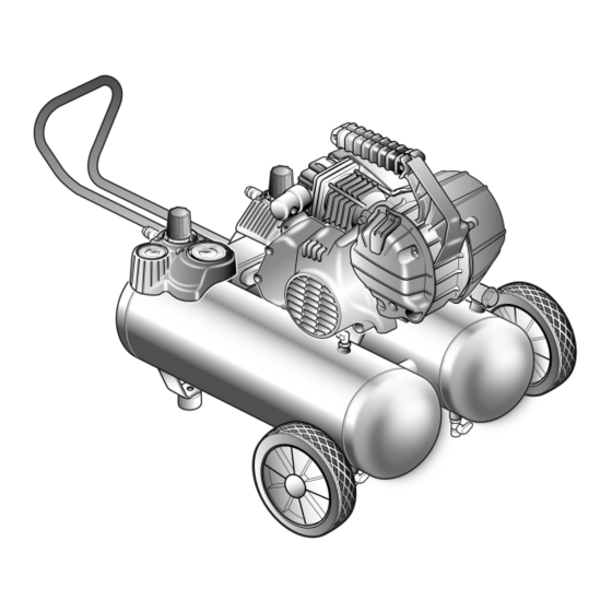
OPERATOR'S MANUAL
5 GALLON PERMALUBE WHEELED AIR COMPRESSOR
HYPRO5-165
CUSTOMER SERVICE
1-866-242-4298
Your air compressor has been engineered and manufactured to FINI's high standard for dependability, ease of operation,
and operator safety. When properly cared for, it will give you years of rugged, trouble-free performance.
WARNING:
To reduce the risk of injury, the user must read and understand the operator's manual before using this product.
Thank you for buying a FINI product.
SAVE THIS MANUAL FOR FUTURE REFERENCE
HYPRO5-165 OM Ver. 06/19
Advertisement
Chapters
Table of Contents

Related Manuals for Fini HYPRO5-165


Summary of Contents for Fini HYPRO5-165
- Page 1 HYPRO5-165 CUSTOMER SERVICE 1-866-242-4298 Your air compressor has been engineered and manufactured to FINI’s high standard for dependability, ease of operation, and operator safety. When properly cared for, it will give you years of rugged, trouble-free performance. WARNING: To reduce the risk of injury, the user must read and understand the operator’s manual before using this product.
-
Page 2: Table Of Contents
IMPORTANT STOP STOP DO NOT RETURN TO STORE This unit was fully tested and inspected prior to shipment and will operate properly when instructions are followed. Refer to your owner’s manual for basic troubleshooting. To avoid unnecessary return to the store, simply call Compressor Support toll free for additional assistance. ... -
Page 3: General Safety Rules
GENERAL SAFETY RULES Additional safety protection will be required in some environments. For example, the working area WARNING: may include exposure to a noise level which can lead to Read and understand all instructions. Failure to hearing damage. The employer and user must ensure follow all instructions listed below may result in electric that any necessary hearing protection is provided shock, fire, and/or serious personal injury. - Page 4 GENERAL SAFETY RULES Never point any tool toward yourself or others. Disconnect the power supply, open the drain valve to decompress the tank and allow water to drain, Keep the exterior of the air compressor dry, clean, and allow the air compressor to become cool to the and free from oil and grease.
-
Page 5: Specific Safety Rules
SPECIFIC SAFETY RULES Know your power tool. Read the operator’s manual Arcing parts. Use spray gun hose at least 25 feet long carefully. Learn its applications and limitations, as well and keep the compressor/motor at least 20 feet away as the specific potential hazards related to this tool. from explosive vapors. -
Page 6: Symbols
SYMBOLS Some of the following symbols may be used on this tool. Please study them and learn their meaning. Proper interpretation of these symbols will allow you to operate the tool better and safer. SYMBOL NAME DESIGNATION / EXPLANATION Volts Voltage. - Page 7 SYMBOLS The following signal words and meanings are intended to explain the levels of risk associated with this product. SYMBOL SIGNAL MEANING Indicates an imminently hazardous situation, which, if not avoided, DANGER: will result in death or serious injury. Indicates a potentially hazardous situation, which, if not avoided, WARNING: could result in death or serious injury.
-
Page 8: Electrical
ELECTRICAL SPEED AND WIRING EXTENSION CORDS The no-load speed of the electric motor varies by model and Use only 3-wire extension cords that have 3-prong specification. The motor speed is not constant and decreases grounding plugs and 3-pole receptacles that accept the under a load or with lower voltage. -
Page 9: Glossary Of Terms
GLOSSARY OF TERMS Air Filter Pressure Switch Porous element contained within a metal or plastic housing Automatically controls the on/off cycling of the compressor. attached to the compressor cylinder head which removes It stops the compressor when the cut-off pressure in the impurity from the intake air of the compressor. -
Page 10: Features
FEATURES PRODUCT SPECIFICATIONS Lubrication ........Permanent Lubricated Oil Running Horsepower ..........1.5 HP Gauges ............1.5 in. diameter Air Tank Capacity ............5 gal. Input........120 V, 60 Hz, AC only, 13.5 Amps Air Pressure ............165 PSI max. Net Weight (compressor only) ........42 lbs. Air Delivery ..........3.2 SCFM @ 90 PSI Duty Cycle ... -
Page 11: Assembly
FEATURES KNOW YOUR AIR COMPRESSOR AIR COMPRESSOR PUMP See Figure 2. To compress air, the piston moves up and down in the cylinder. Before attempting to use this product, familiarize yourself with all On the down stroke, air is drawn in through the air intake valve operating features and safety rules. - Page 12 ASSEMBLY ATTACHING HOSE See Figure 3. Insert the hose into the quick coupler already installed ON/OFF on the compressor (Fig. 3). SWITCH WARNING: Do not attach any tools to the open end of the hose until start-up has been completed. Firmly grasp the open end of the hose;...
-
Page 13: Transport
TRANSPORT TRANSPORT See Figures 6 - 8. Pull telescopic handle out until it locks into place. IMPORTANT: This handle is only for pulling the unit. DO NOT lift the unit by this handle. To collapse the handle, apply pressure for the first few inches to unlock, then slide the handle strait in until it stops. -
Page 14: Operation
OPERATION APPLICATIONS WARNING: Air compressors are utilized in a variety of air system Do not allow familiarity with tools to make you careless. applications. Match hoses, connectors, air tools, and Remember that a careless fraction of a second is accessories to the capabilities of the air compressor. sufficient to inflict serious injury. - Page 15 OPERATION DRAINING THE TANK See Figure 11. Fig. 11 To help prevent tank corrosion and keep moisture out of the air used, the tank of the compressor should be drained daily. To drain: Verify that the compressor is turned off. Holding the handle, tilt the compressor toward the drain valves so that it’s set in a lower position.
- Page 16 OPERATION OVERLOAD PROTECTOR END OF OPERATION/STORAGE This air compressor is equipped with a thermal overload device which will turn the air compressor off automatically, Turn the ON/OFF switch to the OFF (O) position. if the air compressor becomes overheated. If the motor Unplug power cord from wall outlet and wrap around turns OFF repeatedly, check for the following possible handle area to prevent damage when not in use.
-
Page 17: Maintenance
MAINTENANCE Inspect the tank yearly for rust, pin holes, or other WARNING: imperfections that could cause it to become unsafe. When servicing, use only identical replacement parts. Use of any other parts may create a hazard or cause Avoid using solvents when cleaning plastic parts. Most product damage. -
Page 18: Service
SERVICE This compressor is manufactured with a PERMALUBE oil filled crankcase. Under normal operating conditions no maintenance to the oil is required. CAUTION: Use care to avoid tipping the unit over. Oil can leak and damage can occur to the compressor or surrounding items if the compressor is tipped over. -
Page 19: Troubleshooting
TROUBLESHOOTING Problem Possible Cause Solution The compressor does not run. Loss of power or overheating. Check for proper use of extension cord. There is no electrical power being Check to be sure the compressor is plugged supplied to compressor or the power in and the power switch is in the ON position. -
Page 20: Replacement Parts List
REPLACEMENT PARTS LIST PARTS DIAGRAM − AIR COMPRESSOR... - Page 21 REPLACEMENT PARTS LIST AIR COMPRESSOR PARTS LIST − MODEL NO. HYPRO5-165 The model number will be found on a plate attached to air tank. Always mention the model number in all correspondence regarding your PORTABLE AIR COMPRESSOR or when ordering replacement parts.
- Page 22 REPLACEMENT PARTS LIST PARTS DIAGRAM − PUMP UNIT...
- Page 23 REPLACEMENT PARTS LIST PUMP UNIT PARTS LIST − MODEL NO. HY00003 Always mention the model number when ordering replacement parts. KEY NO. CODE DESCRIPTION 9417511 ASSY CRANKCASE/MOTOR ................... 1 9040043 O-RING 2224 ......................1 9417509 CYLINDER ......................... 1 9417501 GASKET CYLINDER-PLATE ..................1 0540051 ASSY VALVE PLATE ....................
-
Page 24: Warranty
HOW TO OBTAIN SERVICE To obtain service for this FINI air compressor you must return it, freight prepaid, to a service center authorized to repair FINI air compressors. You may obtain the location of the service center nearest you by calling (toll free) 1-866-242-4298. - Page 26 OPERATOR’S MANUAL 5 GALLON PERMALUBE WHEELED AIR COMPRESSOR HYPRO5-165 CUSTOMER SERVICE 1-866-242-4298...
- Page 27 1-866-242-4298 Su compresor de aire ha sido diseñado y fabricado de conformidad con las estrictas normas de FINI para brindar fiabilidad, facilidad de uso y seguridad para el operador. Con el debido cuidado, le brindará muchos años de sólido y eficiente funcionamiento.
- Page 28 IMPORTANTE ALTO ALTO NO DEVOLVER A LA TIENDA Esta unidad ha sido comprobada e inspeccionada completamente antes de ser enviada y funcionará correctamente siempre y cuando se sigan las instrucciones. Haga referencia al manual de usuario para la localización y la resolución de los problemas básicos. Para evitar devoluciones innecesarias a la tienda, llame simplemente al número gratuito de Soporte técnico del Compresor para una asistencia adicional.
-
Page 29: Reglas De Seguridad Generales
REGLAS DE SEGURIDAD GENERALES n Tanto el patrón como el operador deben asegurarse ADVERTENCIA: de que se use protección ocular adecuada. Recomendamos una careta protectora de visión Lea y comprenda todas las instrucciones. El amplia encima de los anteojos normales o de los incumplimiento de las instrucciones señaladas abajo anteojos de seguridad que ofrecen protección frontal puede causar descargas eléctricas, incendios y... -
Page 30: Reglas De Seguridad Específicas
REGLAS DE SEGURIDAD GENERALES REGLAS DE SEGURIDAD GENERALES n Purgue lentamente todas las presiones internas del fluidos para frenos, gasolina, productos a base de sistema. El polvo y la basura pueden ser dañinos. petróleo ni solventes fuertes para limpiar la unidad. n Guarde las herramientas que no estén en uso Con el cumplimiento de esta regla se reduce el riesgo fuera del alcance de los niños y de toda persona... - Page 31 REGLAS DE SEGURIDAD ESPECÍFICAS Siempre desconecte el suministro de aire y el de Nunca use un adaptador eléctrico con esta clavija de corriente antes de efectuar ajustes, dar servicio a la conexión a tierra. herramienta o cuando no esté usándose ésta. Revise para ver si hay piezas dañadas.
-
Page 32: Símbolos
SÍMBOLOS Es posible que se empleen en esta herramienta algunos de los siguientes símbolos. Le suplicamos estudiarlos y aprender su significado. Una correcta interpretación de estos símbolos le permitirá utilizar mejor y de manera más segura la herramienta. SÍMBOLO NOMBRE DENOMINACIÓN/EXPLICACIÓN Volts Voltaje. - Page 33 SÍMBOLOS Las siguientes palabras de señalización y sus significados tienen el objeto de explicar los niveles de riesgo relacionados con este producto. SÍMBOLO SEÑAL SIGNIFICADO Indica una situación peligrosa inminente, la cual, si no se evita, PELIGRO: causará la muerte o lesiones serias. Indica una situación peligrosa posible, la cual, si no se evita, ADVERTENCIA: podría causar la muerte o lesiones serias.
-
Page 34: Aspectos Eléctricos
ASPECTOS ELÉCTRICOS CORDONES DE EXTENSIÓN VELOCIDAD Y CABLEADO Sólo utilice cordones de extensión de tres conductores con La velocidad en vacío del motor eléctrico varía por el modelo clavijas de tres patillas y receptáculos de tres polos que acepten y la especificación. La velocidad del motor no es constante y disminuye durante el corte o con un voltaje bajo. -
Page 35: Glosario De Términos
GLOSARIO DE TÉRMINOS Filtro de aire Perilla de regulación de presión Es un elemento poroso contenido dentro de un Sirve para regular la presión de la salida de aire dirigida a alojamiento de metal o plástico unido al cilindro de la la herramienta. -
Page 36: Características
CARACTERÍSTICAS ESPECIFICACIONES DEL PRODUCTO Potencia de funcionamiento ........1,5 HP Lubricación ....Lubricación permanente con aceite Capacidad del tanque de aire......19 L. (5 gal.) Manómetros......3,8 cm (1,5 pulg.) de diámetro Presión de aire ......1137,6 kPa (165 psi) máx. Corriente de entrada.. -
Page 37: Armado
CARACTERÍSTICAS FAMILIARÍCESE CON EL COMPRESOR BOMBA DEL COMPRESOR DE AIRE Vea la figura 2. Para comprimir el aire, el pistón sube y baja en el cilindro. En Antes de intentar utilizar este producto, familiarícese con todas la carrera descendente, la válvula de admisión aspira aire del las características de funcionamiento y normas de seguridad de exterior mientras la válvula de escape permanece cerrada. - Page 38 ARMADO CÓMO CONECTAR LA MANGUERA Vea la figura 3. Introduzca entonces el tubo de PVC en el acoplador INTERRUPTOR rápido ya conectado en el compresor (Fig. 3). DE ENCENDIDO/ APAGADO ADVERTENCIA: No conecte las herramientas en el extremo abierto de la manguera sin haber efectuado el procedimiento inicial.
-
Page 39: Transporte
TRANSPORTE TRANSPORTE Vea las figuras 6 , 7 y 8. Tire telescópica manillar hacia fuera hasta que enganche en posición. IMPORTANTE: Este manillar es sólo para halar la unidad. NO ES para usar como asa para levantarla. Para plegar el mango, aplicar presión en las primeras pulgadas para desbloquear luego deslizar el mango derecho hacia adentro hasta que se detenga. -
Page 40: Funcionamiento
FUNCIONAMIENTO USOS Los compresores de aire se utilizan en una veriedad de sistemas de ADVERTENCIA: suministro de aire. Las mangueras, conectores, herramientas de aire y No permita que su familarización con las herramientas lo accesorios deben corresponder a la capacidad del compresor de aire. vuelva descuidado. - Page 41 FUNCIONAMIENTO DRENADO DEL TANQUE Vea la figura 11. Fig. 11 Como ayuda para impedir la corrosión del tanque y mantener el aire libre de humedad, debe drenarse diariamente el tanque del compresor. Para drenar el tanque: Asegúrese de que el compresor está apagado. Sujetándolo por la manilla, inclinar el compresor hacia las válvulas de drenaje de tal manera que éste se encuentre en la posición más baja.
- Page 42 FUNCIONAMIENTO PROTECTOR CONTRA LA SOBRECARGA FIN DE LA OPERACIÓN / ALMACENAMIENTO Este compresor de aire está provisto de un dispositivo Asegúrese de que el interruptor de alimentación de térmico de sobrecarga que desactivará el compresor de encendido y apagado (ON/OFF) se encuentra en la aire de forma automática si este se calienta en exceso.
-
Page 43: Mantenimiento
MANTENIMIENTO Evite el empleo de solventes al limpiar piezas de plástico. ADVERTENCIA: La mayoría de los plásticos son susceptibles a diferentes tipos de solventes comerciales y pueden resultar dañados. Al dar servicio a la unidad, sólo utilice piezas de repuesto idénticas. El empleo de piezas diferentes Utilice paños limpios para eliminar la suciedad, el polvo, el puede causar un peligro o dañar el producto. -
Page 44: Servicio
SERVICIO Este compresor se fabrica con un cárter lleno de aceite PERMALUBE. Bajo condiciones de trabajo normales el aceite no requiere mantenimiento. PRECAUCIÓN: Tener cuidado para evitar volcar la unidad. Si el compresor se vuelca, el aceite podría derramarse y dañar el compresor o los elementos a su alrededor. -
Page 45: Solución De Problemas
SOLUCIÓN DE PROBLEMAS Problema Causa Solución El compresor no arranca El tanque tiene suficiente presión. El compresor se enciende cuando la presión del tanque desciende a la presión de ananque. No hay energía elétrica. Asegurase de que la unidad esté enchufada. Fusibles de casa/taller fundidos. -
Page 46: Lista De Piezas De Repuesto
LISTA DE PIEZAS DE REPUESTO DIAGRAMA DE LAS PIEZAS – COMPRESOR DE AIRE... - Page 47 LISTA DE PIEZAS DE REPUESTO LISTA DE PIEZAS − COMPRESOR DE AIRE - N. DE MODELO HYPRO5-165 El número de modelo se encuentra en una placa adherida al tanque de aire. Siempre mencione el número del modelo en toda correspondencia relacionada con el COMPRESOR DE AIRE PORTÁTIL o al hacer pedidos de piezas de repuesto.
- Page 48 LISTA DE PIEZAS DE REPUESTO DIAGRAMA DE LAS PIEZAS - BOMBA...
- Page 49 LISTA DE PIEZAS DE REPUESTO LISTA DE PIEZAS DE LA BOMBA - N. DE MODELO HY00003 Mencionar siempre el número de modelo cuando se hace un pedido de piezas de repuesto. NÚM. REF. NÚM. PIEZA DESCRIPCIÓN CANT. 9417511 CONJUNTO MOTOR/CRÁTER ................. 1 9040043 O-RING 2224 ......................
-
Page 50: Garantía
- que puedan ser impuestas por la legislación del estado se limitan a dos años a partir de la fecha de compra. FINI no se hace responsable de ningún daño directo, indirecto, accidental, especial ni de daños y perjuicios. - Page 52 MANUAL DEL USUARIO COMPRESOR DE AIRE TRANSPORTABLE CON LUBRICACIÓN PERMANENTE CON TANQUE DE 19 LITROS (5 GALONES) HYPRO5-165 SERVICIO DE CLIENTE 1-866-242-4298 9070208...
Need help?
Do you have a question about the HYPRO5-165 and is the answer not in the manual?
Questions and answers