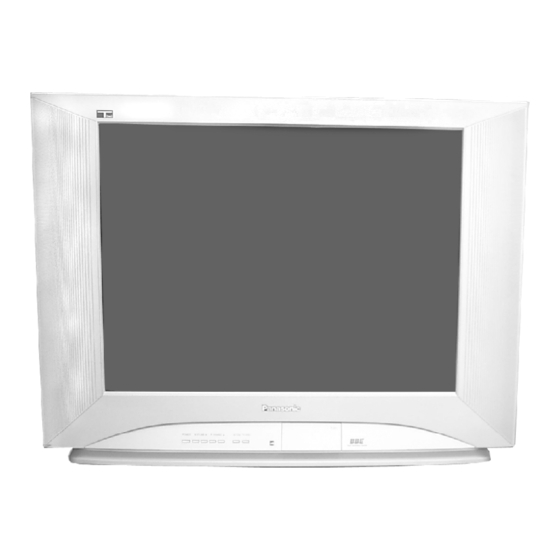
Panasonic CT-24SL14J Service Manual
Hide thumbs Also See for CT-24SL14J:

Advertisement

Quick Links

This simplified service manual is issued to add listed models to the NA10 family service manuals order
No.MTNC030733A1(CT-27SL13G), MTNC030834A1(CT-24SL13G) & MTNC030623C1(CT-25L8G). A complete
parts list and schematics are included in this simplified service manual. Please file and use this simplified
service
manual
together
MTNC030834A1(CT-24SL13G) and main service manual order No. MTNC030623C1 (CT-25L8G).
CONTENTS
CT-24SL14J
CT-24SL14UJ
CT-27SL14J
CT-27SL14UJ
GN3 (NA10)
with
simplified
service
Page
3
4
5
5
6
manuals
MTNC030733A1(CT-27SL13G),
Copyright 2004 Matsushita Electric Corporation of
America. All rights reserved. Unauthorized copying
and distribution is a violation of law.
MTNC040108A1
Color Television
Page
B05
7
7
8
9
9

Advertisement

Table of Contents
loading

Summary of Contents for Panasonic CT-24SL14J

  • Page 1: Table Of Contents

    MTNC040108A1 Color Television CT-24SL14J CT-24SL14UJ CT-27SL14J CT-27SL14UJ GN3 (NA10) This simplified service manual is issued to add listed models to the NA10 family service manuals order No.MTNC030733A1(CT-27SL13G), MTNC030834A1(CT-24SL13G) & MTNC030623C1(CT-25L8G). A complete parts list and schematics are included in this simplified service manual. Please file and use this simplified...
  • Page 2 9 Dissasembly for service 15.2. A-Board printed circuit (2 of 2) 9.1. Disassembly for CRT replacement 15.3. C-Board printed circuit 9.2. Back cover removal 16 Block diagrams 9.3. Inside View 16.1. Video Signal Block Diagram 10 Chassis service adjustment procedures 16.2.
  • Page 3: Safety Precautions

    1 Safety precautions Connect a 1.5kΩ 10 watt resistor in parallel with a 0.15µF General guidelines capacitor between an exposed metallic part and ground. An isolation transformer should always be used during the Use earth ground, for example a water pipe. servicing of a receiver whose chassis is not isolated from AC power line.
  • Page 4: Service Notes

    2 Service notes NOTE How to replace flat IC (required tools) These components are affixed with glue. Be careful not to 1. Remove the solder from all of the pins of a Flat IC by break or damage any foil under the component or at the using a desolder braid pins of the ICs when removing.
  • Page 5: X-Ray Protection Circuit Check & Adjustments

    3 EEPROM replacement IMPORTANT To protect against possible damage to the solid state If a new EEPROM integrated circuit is replaced for servicing, devices due to arching or static discharge, make certain follow the next procedure once that the memory is properly that all ground wires and CRT DAG wire are securely assembled: connected.
  • Page 6: About Lead Free Solder (Pbf)

    4 About lead free solder (PbF) NOTE Lead is listed as (Pb) in the periodic table of elements. In the information below, Pb will refer to lead solder, and PbF will refer to Lead Free Solder. The lead free solder used in our manufacturing process and discussed below is (Sn+Ag+Cu). That is Tin (Sn), Silver (Ag) and Copper (Cu) although other types are available.
  • Page 7: Receiver Feature Table

    29.69x21.03x23.68in WEIGHT (Kg/Lbs) 34 / 74.95 35.4 / 78.04 Note: Specifications are subject to change without notice or obligation. Dimensions and weights are approximate. 6 Board description table CT-24SL14J / CT-24SL14UJ BOARD PART NUMBER DESCRIPTION TNP2AH060DB MAIN BOARD TNP2AA157AN CRT BOARD...
  • Page 8: Tv Location Of Controls

    7 TV Location of controls...
  • Page 9: Location Of Controls (Remote)

    8 Location of controls (remote) 8.1. EUR7613ZB0 Note: For additional information about this remote please refer to the owner’s manual section remote operation, listed on the parts list section.
  • Page 10 9 Dissasembly for service 4. Remove the C-Board from the CRT base and unplug the black wires (CRT dag ground) C11 & C21. Back cover 5. Disconnect the speakers plug from the A-Board. Remove all the screws marked with an arrow (←) from the 6.
  • Page 11 9.2. Back cover removal Back Cover 9.3. Inside View...
  • Page 12 10 Chassis service adjustment procedures All service adjustments are factory preset and should not Note: require adjustment unless controls and/or associated Connect the (-) lead of the voltmeter to the appropriate components are replaced. ground. Use IC801’s heat sink when the HOT ground symbol is used.
  • Page 13 11 Service mode (electronic adjustments) This receiver has electronic technology using the IC bus tuned to channel 3 with a preset level of sound. concept. It performs as a control function and it replaces many Any programmed channels, channels caption data and mechanical controls.
  • Page 14 11.1. Service adjustment default values for items NAME DESCRIPTION REGISTER VALUE CT-24SL14J/UJ CT-27SL14J/UJ MTSIN MTS INPUT LEVEL SEPAL MTS LOW LEVEL SEPARATION SEPAH MTS HIGH LEVEL SEPARATION CLOCK CLOCK HHSTH HHS VOLTAGE LEVEL REFERENCE COLOR COLOR 00 F0 TINT TINT...
  • Page 15 12 Service adjustments (electronic controls) NOTE PREPARATION Please correlate with available pattern on all adjustments 1. Normalize the picture settings. 2. Set the BRIGHTNESS control to minimum. 12.1. Sub-Brightness and Contrast 3. Set the COLOR control to the center. Service DAC adjustment 4.
  • Page 16 3. In service mode adjust “TINT” data so that the color 6. Turn screen clockwise slowly until color is slightly does not become greenish or redish. appeared. 7. Then adjust “CUT R” and “CUT B” until line becomes 4. In service mode adjust “COLOR” data so that the color level is not too high (saturated) or too low (tending to white.
  • Page 17 12.5.2. Vertical linearity(V-C), V-Size and V-Position adjustment PREPARATION 1. Apply a crosshatch pattern 2. Normalize the picture settings. PROCEDURE 1. Enter service mode, select DAC adjustment “V-POS” and adjust monoscope pattern to the center vertical position of the CRT center mark. V-Adjustment 2.
  • Page 18 12.6. MTS circuit adjustments SW ON. 5. Adjust the MTS High-level separation adjustment The MTS circuit adjustments require two steps: “SEPAH” until the amplitude displayed on the scope 1. Input level adjustment. is minimum. 2. Stereo separation adjustment. 6. Repeat above steps 2 through 5 until the amplitude is at minimum for both signals.
  • Page 19 13 Identification of main components 13.1. A-Board main components A-Board main components 13.2. C-Board main components C-Board main components...
  • Page 20 14 Reference for PDF colors...
  • Page 21 15 Conductor views...
  • Page 22 15.1. A-Board printed circuit (1 of 2) A-BOARD 1 of 2 TNP2AH060 CT-24SL14J/UJ, CT-27SL14J/UJ...
  • Page 23 15.2. A-Board printed circuit (2 of 2) A-BOARD 2 of 2 TNP2AH060 CT-24SL14J/UJ, CT-27SL14J/UJ...
  • Page 24 15.3. C-Board printed circuit C-BOARD TNP2AA157 CT-24SL14J/UJ, CT-27SL14J/UJ...
  • Page 25 16 Block diagrams...
  • Page 26 MCOMP IN MV IN MU IN IC001 JK3002 FRONT VIDEO R OUT G OUT B OUT VM OUT MSCIN JK3003 Q361 Q362 Q360 S-VIDEO Q358 Q359 Q357 Q354 Q355 Q356 R-IN G-IN B-IN IC351 R-OUT G-OUT B-OUT C-BOARD CT-24SL14J/UJ, CT-27SL14J/UJ MODELS...
  • Page 27 Audio Switching IC3101 L&R Mixed MPX IN IC2201 JK3001 R-OUT L-OUT REAR AUDIO R-IN L-IN IC2501 R-OUT L-OUT JK3002 R-IN L-IN FRONT VAO-R AUDIO IC2301 AUDIO AMP VAO-L R-OUT L-OUT MUTE JK3004 TO AUDIO SP ON/OFF IC001 CT-24SL14J/UJ, CT-27SL14J/UJ MODELS...
  • Page 28 17 Schematics...
  • Page 29 17.1. English schematic notes...
  • Page 30 17.2. Notas de esquemáticos en español...
  • Page 31 17.3. A-Board schematic TNP2AH060DB (1 of 4) A-BOARD 1 of 4 TNP2AH060DB CT-24SL14J / CT-24SL14UJ...
  • Page 32 17.4. A-Board schematic TNP2AH060DB (2 of 4) A-BOARD 2 of 4 TNP2AH060DB CT-24SL14J / CT-24SL14UJ...
  • Page 33 17.5. A-Board schematic TNP2AH060DB (3 of 4) A-BOARD 3 of 4 TNP2AH060DB CT-24SL14J / CT-24SL14UJ...
  • Page 34 17.6. A-Board schematic TNP2AH060DB (4 of 4) A-BOARD 4 of 4 TNP2AH060DB CT-24SL14J / CT-24SL14UJ...
  • Page 35 17.7. A-Board schematic TNP2AH060MA (1 of 4) A-BOARD 1 of 4 TNP2AH060MA CT-27SL14J / CT-27SL14UJ...
  • Page 36 17.8. A-Board schematic TNP2AH060MA (2 of 4) A-BOARD 2 of 4 TNP2AH060MA CT-27SL14J / CT-27SL14UJ...
  • Page 37 17.9. A-Board schematic TNP2AH060MA (3 of 4) A-BOARD 3 of 4 TNP2AH060MA CT-27SL14J / CT-27SL14UJ...
  • Page 38 17.10. A-Board schematic TNP2AH060MA (4 of 4) A-BOARD 4 of 4 TNP2AH060MA CT-27SL14J / CT-27SL14UJ...
  • Page 39 17.11. C-Board schematic TNP2AA157AN/AR (1 of 2) C-BOARD 1 of 2 TNP2AA157AN/AR CT-24SL14J/UJ, CT-27SL14J/UJ...
  • Page 40 17.12. C-Board schematic TNP2AA157AN/AR (2 of 2) C-BOARD 2 of 2 TNP2AA157AN/AR CT-24SL14J/UJ, CT-27SL14J/UJ...
  • Page 41 ..0.00 ..0.40 ..0.00 ..4.90 ..0.40 ..3.30 ..9.00 CT-24SL14J/UJ, CT-27SL14J/UJ...
  • Page 42 ..2.50 Q956 Q957 Q958 Q961 Q962 . . . 216.80 0.80 5.80 5.70 0.30 2.40 . . . 145.30 65.20 0.00 8.90 1.80 8.90 . . . 152.70 0.30 6.30 5.10 0.00 1.90 . . . 151.00 CT-24SL14J/UJ, CT-27SL14J/UJ...
  • Page 43 A12 PIN 2 (HEATER) IC501 PIN 4 (H-DRIVE) IC451 PIN 3 (PUMP UP) IC451 PIN 5 (V OUT) 2.76 Vp-p 408 Vp-p 110 Vp-p .508 KVp-p IC801 PIN 7 IC801 PIN 1 Q501 Collector Q551 Collector (H OUT) CT-24SL14J/UJ, CT-27SL14J/UJ...
  • Page 44 18 Parts location...
  • Page 45 19 Parts list 19.1. Parts list notes...
  • Page 46 CAP P .10UF-J-100V C008 TCJ2VF1H103Z CAP C .01UF-Z-50V C462 TCJ2VF1H103Z CAP C .01UF-Z-50V CT-27SL14J CT-27SL14UJ C009 ECJ2VB1C104K CAP C .1UF-K-16V CT-24SL14J CT-24SL14UJ C462 TCJ2VF1H683Z CAP C 68UF-Z-50V CT-24SL14J CT-24SL14UJ C009 ECJ2VF1H104Z CAP C .1UF-Z-50V C501 ECJ2VB1H221K CAP C 220PF-K-50V C010...
  • Page 47 Ref. Part No. Part Name & Description Remarks Ref. Part No. Part Name & Description Remarks C806 ECQM4103KZW CAP P .01UF-K-400V C2507 TCJ2VB1H472K CAP C 4700PF-K-50V C808 ECA1HM470B CAP E 47UF-50V C2508 TCJ2VB1H472K CAP C 4700PF-K-50V C809 TACCW471T50V CAP C 470PF-K-50V C2509 ECJ2VB1C104K CAP C .1UF-K-16V...
  • Page 48 HORIZONTAL LINEARITY COIL D2305 CVS20B120MTA DIODE ZENER CT-27SL14J CT-27SL14UJ D2307 CVS20B120MTA DIODE ZENER L551 ELH5L7139 HORIZONTAL LINEARITY COIL D2350 MAZ41000LF DIODE ZENER CT-24SL14J CT-24SL14UJ D2353 MA2C165001VT DIODE L552 EXCELSA39V EMI BEAD CORE D2354 MA2C165001VT DIODE L558 ELC10D471E CHOKE COIL D2355...
  • Page 49 R019 ERJ6GEYJ472V RES M 4.7K-J-1/10W R360 ERDS1TJ104T RES C 100K-J-1/2W R020 ERJ6GEYJ221V RES M 220-J-1/10W R361 EROS2THF5601 RES M 5.6K-F-1/4W CT-24SL14J CT-24SL14UJ R021 ERJ6GEYJ101V RES M 100-J-1/10W R361 EROS2THF6801 RES M 6.8K-F-1/4W R022 ERJ6GEYJ101V RES M 100-J-1/10W CT-27SL14J CT-27SL14UJ R023...
  • Page 50 RES C 12K-J-1/4W CT-27SL14J CT-27SL14UJ R716 ERDS2TJ101T RES C 100-J-1/4W R452 ERDS1FJR68P RES C .68-J-1/2W R756 ERG2FJ820H RES M 82-J-2W CT-24SL14J CT-24SL14UJ R761 ERDS2TJ102T RES C 1K-J-1/4W R453 ERJ6GEYJ303V RES M 30K-J-1/10W R762 ERDS2TJ472T RES C 4.7K-J-1/4W CT-24SL14J CT-24SL14UJ R802...
  • Page 51 RES M 75.0-F-1/10W TNR001 ENG36A10GF TUNER R3010 ERJ6GEYJ334V RES M 330K-J-1/10W A60LVY196X-D CRT 24” WITH DEFLECTION YOKE R3013 ERJ6ENF75R0V RES M 75.0-F-1/10W CT-24SL14J CT-24SL14UJ R3014 ERJ6ENF75R0V RES M 75.0-F-1/10W M68LZP195X CRT 27” CT-24SL14J CT-24SL14UJ CT-27SL14J CT-27SL14UJ R3015 ERJ6ENF75R0V RES M 75.0-F-1/10W M001...
  • Page 52 Ref. Part No. Part Name & Description Remarks TXFKY08JSER FRONT CABINET CT-27SL14J CT-27SL14UJ TXFKY09JSER FRONT CABINET CT-24SL14J CT-24SL14UJ TXFKU14GSER BACK CABINET CT-27SL14J CT-27SL14UJ TXFKU02JSER BACK CABINET CT-24SL14J CT-24SL14UJ JK3001 TJB2AA0221 A/V 8 PIN TERMINAL JK3002 TJB2AA0045 FRONT A/V TERMINAL JK3003...

This manual is also suitable for:

Ct-24sl14ujCt-27sl14jCt-27sl14ujCt-27sl14

Table of Contents