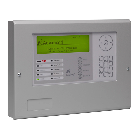
Advanced MxPro4 Manual
Sounder booster
Hide thumbs
Also See for MxPro4:
- Manual (72 pages) ,
- Installation sheet & quick reference manual (4 pages) ,
- Manual (12 pages)
Advertisement
Sounder Booster
Features
The Advanced 4A Sounder Booster (Mxp-026) is a peripheral unit that takes a standard sounder circuit from
either a control panel or other panel based sounder circuit controller and provides increased sounder output
capability.
This boosted output is fully monitored for open and short circuits and will take an independent supply to
provide up to 4 Amps of sounder drive current to a single circuit.
On board indication via 2 LED indicators located on the booster PCB enable the user to view when an output
has been triggered and when an external power supply has been connected
Features
The unit is available in 2 formats:
The Mxp-026 is a booster card only for mounting in a customer's / OEM enclosure or within an MxPro
4 multi-loop panel.
The Mxp-026-BXP is a booster card and a 5 Amp EN54-4 power supply mounted together in a metal
enclosure.
www.advancedco.com
Advertisement
Table of Contents

Subscribe to Our Youtube Channel
Summary of Contents for Advanced MxPro4
- Page 1 Sounder Booster Features The Advanced 4A Sounder Booster (Mxp-026) is a peripheral unit that takes a standard sounder circuit from either a control panel or other panel based sounder circuit controller and provides increased sounder output capability. This boosted output is fully monitored for open and short circuits and will take an independent supply to provide up to 4 Amps of sounder drive current to a single circuit.
- Page 2 Specifications & Ordering: Models, Sales Order Parts: Mxp-026-BXP : 4A Sounder Card Boxed with 5A PSU Mxp-026 4A Sounder Booster Card (Requires a minimum 4 Amp power supply and enclosure) Applications / Limitations: The sounder booster is used where a single sounder output circuit of up to 4 Amps is required. Each of the panel’s sounder outputs can only monitor a single circuit.
- Page 3 Table of Contents Page WIRING CONFIGURATION ........................... 3 FAULT INDICATION ............................4 1 Wiring Configuration The diagram below shows a ‘typical’ application for the 4A sounder booster. Note that a 10KΩ EOL resistor must be fitted to the end of the boosted sounder output circuit to maintain correct fault monitoring. 10K EOL resistor must be fitted to the end of the boosted...
- Page 4 2 Fault Indication Any open circuit condition between the ‘FAULT I/P’ terminals will result in the panel indicating a ‘Sounder Open Circuit’ fault. When the ‘FAULT I/P’ terminals are connected to the PSU’s ‘Fault’ relay, the panel will indicate a ‘Sounder Open Circuit’...
- Page 5 USER NOTES www.advancedco.com...
- Page 6 Doc Number: 680-052 Revision: Advanced Electronics Ltd Moorland Way, Cramlington, Northumberland, NE23 1WE UK First Issued: 2013-mm-dd Tel: +44 (0)1670 707 111 Fax: +44 (0)1670 707 222 Email: sales@advancedco.com Web: www.advancedco.com www.advancedco.com...


Need help?
Do you have a question about the MxPro4 and is the answer not in the manual?
Questions and answers