Table of Contents
Advertisement
Quick Links
Advertisement
Table of Contents
Troubleshooting

Related Manuals for ep ICE301B


Summary of Contents for ep ICE301B
- Page 1 Service Manual ICE301B Electric Forklift Truck...
- Page 2 Version No. Changes (Serial number) 2020-09-12 SM-3132 09.20 EP V1 Service Manual If there are any changes, revised version will be published once every 12 months; if there is no change, please follow the most recent version. Please refer to the corresponding version of the service manual against the purchase time ICE301B of your vehicle.
-
Page 3: Table Of Contents
4.2.1 Removal and Installation ..........36 4.2.3 Checking and Testing .............37 Copyright 4.3 Drive Axle ................38 Copyright of Service Manual belongs to EP Equipment Co., Ltd. 4.3.1 Removal and Installation ..........38 4.3.2 Component..............39 4.3.3 Gear Oil ................40 EP Equipment Co., Ltd. - Page 4 TABLE OF CONTENTS TABLE OF CONTENTS TABLE OF CONTENTS TABLE OF CONTENTS SECTION PAGE SECTION PAGE 5. STEERING SYSTEM ............45 8.1.1 Removal and Installation ..........72 8.1.2 Lifting Chains ..............73 5.1 Rear Steering Wheel ............47 8.1.2.1 Chain Adjustment ............73 5.1.1 Removal and Installation ..........47 8.1.2.2 Chain Replacement.............74 5.2 Steering Bridge ..............48...
- Page 5 SAFETY WARNING 1. INFORMATION & SPECIFICATIONS For your own safety and that of others, please observe the following safety instructions: Thorough and normative maintenance is one of the most important prerequisites to ensure stable and reliable operation of truck. Neglecting regular maintenance could easily lead to the truck malfunction and failure, and potential threats to staff and operational safety.
-
Page 6: Information & Specifications
INFORMATION & SPECIFICATIONS NOTE: 1.1 After-sales Service Platform Claims/Replacement Parts Service Platform: After-sales Maintenance Service Platform: NOTE In order to provide you with a fast and efficient after-sales service, when you claim / order spare parts or after-sales service upon maintenance, please provide accurate truck model, vehicle body serial number and part number. -
Page 7: Introduction
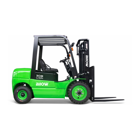
INFORMATION & SPECIFICATIONS INFORMATION & SPECIFICATIONS 1.2 Introduction This series are electric forklift trucks. Its impor- tant structure is as shown in Fig3132-00003SM. WARNING - Please refer to the nameplate for rated load capacity of the vehicle. - The vehicle can only be used on the level gro- und indoors, never use it on mezzanine or balcony area. -
Page 8: General Tightening Torques
INFORMATION & SPECIFICATIONS INFORMATION & SPECIFICATIONS 1.4 General Tightening Torques Table 1.4.2 Metric Screws/Bolts Tightening Torque Table (n•m) Screws or bolts used on the truck are of 8.8 Performance Level grade or higher performance level. 10.9 12.9 Nominal Diameter When you are conducting truck maintenance, you can refer to Table 1.4.1 and Table 1.4.2 to (mm) Proof Stress (MPa) -
Page 9: Maintenance
INFORMATION & SPECIFICATIONS 2. MAINTENANCE REV. 09/2020... -
Page 10: Overview
MAINTENANCE NOTE: 2.1 Overview NOTE Only by performing regular vehicle maintenance Under harsh working conditions: such as, the and repair, can ensure the continuous and external temperature is too high or too low, reliable use of the truck. dusty, or implementing multiple shifts per day, Only specially trained and qualified personnel the maintenance and care interval should be a r e c a p a b l e o f m a i n t e n a n c e a n d r e p a i r... -
Page 11: Cleaning
MAINTENANCE MAINTENANCE 2.2 Maintenance Regular inspection and maintenance under Table 2.1 Inspection & Maintenance List harsh conditions of use: 2.2.1 Cleaning Interval in days/months/years 60 d 90 d Under harsh working conditions, especially: - Dusty environment Interval in hours 1000 2000 Do not use flammable liquids to clean the - Corrosive environment... - Page 12 MAINTENANCE MAINTENANCE Table 2.1 Inspection & Maintenance List (Continued) Table 2.1 Inspection & Maintenance List (Continued) Interval in days/months/years 60 d 90 d Interval in days/months/years 60 d 90 d Interval in hours 1000 2000 Interval in hours 1000 2000 Power Supply &...
-
Page 13: Lubrication
MAINTENANCE MAINTENANCE 2.2.3 Lubrication Please see Table 2.2 for the lubricants used in Table 2.1 Inspection & Maintenance List (Continued) this truck. Lubricant Interval in days/months/years 60 d 90 d CAUTION Improper operations may constitute hazards Interval in hours 1000 2000 to the operator's health and life, as well as to The use and disposal of lubricants must be... -
Page 14: Troubleshooting
MAINTENANCE Table 2.2 Lubricants 3. TROUBLESHOOTING Code Type Specification Amount Position Hydraulic Anti-wear hydraulic oil L-HM46 See Table 2.3 System Sliding surface Multi-purpose grease Polylub GA352P Appropriate amount (See Table 2.4) Heavy duty gear oil 85W-90GL-5 4.5L (Align with oiling port) Drive Axle After the gas within the system is completely... -
Page 15: Preparation Before Troubleshooting
TROUBLESHOOTING NOTE: 3.1 Preparation Before Troubleshooting Park the truck on level ground and block the CAUTION wheels with wooden wedges; Fully lower the forks and press the emergen- If the battery voltage is still abnormal after being cy stop switch. charged: open the battery compartment, check the voltage of each battery and its connection Turn off the key switch;... -
Page 16: Troubleshooting Solutions Of Common Faults
TROUBLESHOOTING TROUBLESHOOTING 3.2 Troubleshooting Solutions of Common Faults Table 3.1 Troubleshooting of Common Faults Table 3.1 lists the common faults that may occur and handling methods. Mainly consists of the following items: Fault Fault Symptom Probable Causes Troubleshooting Table 3.1 Troubleshooting of Common Faults 4. - Page 17 TROUBLESHOOTING TROUBLESHOOTING Table 3.1 Troubleshooting of Common Faults Table 3.1 Troubleshooting of Common Faults Fault Fault Symptom Probable Causes Troubleshooting Fault Fault Symptom Probable Causes Troubleshooting • Insufficient voltage of battery; Check the voltage of battery; • Overload; 2. Refer to the rated capacity 1.
- Page 18 TROUBLESHOOTING TROUBLESHOOTING Table 3.1 Troubleshooting of Common Faults (continued) Table 3.1 Troubleshooting of Common Faults Fault Fault Symptom Probable Causes Troubleshooting Fault Fault Symptom Probable Causes Troubleshooting • Overload 1. Refer to the rated capacity 1. Check the hydraulic oil level. •...
- Page 19 TROUBLESHOOTING TROUBLESHOOTING Table 3.1 Troubleshooting of Common Faults (continued) Table 3.1 Troubleshooting of Common Faults (continued) Fault Fault Symptom Probable Causes Troubleshooting Fault Fault Symptom Probable Causes Troubleshooting • Insufficient hydraulic oil; 1. Replace the hydraulic oil; • Grease stiffened or dirt 1.
- Page 20 TROUBLESHOOTING TROUBLESHOOTING Table 3.1 Troubleshooting of Common Faults (continued) Table 3.1 Troubleshooting of Common Faults (continued) Fault Fault Symptom Probable Causes Troubleshooting Fault Fault Symptom Probable Causes Troubleshooting Controller failure error, carry out 1. Check the light and its cir- troubleshooting according to the a.
- Page 21 TROUBLESHOOTING 4. DRIVING SYSTEM REV. 09/2020...
-
Page 22: Driving System
DRIVING SYSTEM NOTE: 4.1 Drive Wheel - Unscrew the six nuts (2) and remove the drive wheel assembly (3). 4.1.1 Removal and Installation Removal Installation - Turn off the truck power and remove the key; - Install according to the reverse order of rem- - Place the jack (1) under the chassis near the oval. -
Page 23: Drive Motor
DRIVING SYSTEM DRIVING SYSTEM 4.2 Drive Motor 4.2.3 Checking and Testing U, V, W Terminals This truck obtains drive force through AC motor. - Identify if the motor windings are normal through measuring the resistance of U-V, V-W, and U-W respectively, if there is short circuit or breakage;... -
Page 24: Drive Axle
DRIVING SYSTEM DRIVING SYSTEM 4.3 Drive Axle Installation - Install according to the reverse order of rem- 4.3.1 Removal and Installation oval. Removal - Loosen the oil drain plug and drain all gear oil; - Power off the truck and remove the key; CAUTION - Unscrew the twelve bolts (7) and remove the - Remove the drive wheel;... -
Page 25: Differential
DRIVING SYSTEM DRIVING SYSTEM 4.3.3 Gear Oil 4.4 Differential CAUTION Check gear oil level 4.4.1 Removal and Installation Gear oil may damage truck parts and con- Loosen the oiling port plug (1, Fig3132- Removal (Fig3132-20009SM) taminate the environment. When replace the 20011SM) and observe the oil level;... -
Page 26: Removal And Installation
DRIVING SYSTEM DRIVING SYSTEM 4.5 Gearbox 4.6 Accelerator Pedal 4.5.1 Removal and Installation 4.6.1 Removal and Installation Removal (Fig3132-20004SM) - Power off the truck and remove the key; - Remove the drive assembly from the chassis - Remove the cushion; and dismantle the drive axle;(see Section - Disconnect the connection between the... -
Page 27: Checking And Testing
DRIVING SYSTEM 4.6.3 Checking and Testing - Press the accelerator pedal. Measure the vol- 5. STEERING SYSTEM tage between the interfaces with a multimeter. Checking as shown in the following table: - Check if the accelerator pedal is reset pro- perly, also check for damage;... -
Page 28: Rear Steering Wheel
STEERING SYSTEM NOTE: 5.1 Rear Steering Wheel - Unscrew the eight nuts (1,Fig3530-10002SM) and remove the steering wheel assembly (2) 5.1.1 Removal and Installation from the steering bridge (3). Removal - Turn off the truck power and remove the key; - Place the jack (1) under the chassis near steering wheels, make the wheel off the ground;... -
Page 29: Steering Bridge
STEERING SYSTEM STEERING SYSTEM 5.2.2 Component - Turn the wheel to see if it is rotating smoothly, - Unscrew the four bolts (2) and remove the fix and if there is blocking or not; plate (3), then dismantle the steering bridge (5) from the chassis;... -
Page 30: Steering Cylinder
STEERING SYSTEM 5.3 Steering Cylinder - Secure the cylinder to hose clamp and gently clamp the cylinder middle; 6. BRAKE SYSTEM 5.3.1 Removal and Installation - Unscrew the cylinder cap (1,Fig3132- 70005SM) from side with cylinder wrench; Removal - Remove the circlip (2), snap ring (3), dust ring - Turn off the truck power and remove the key;... -
Page 31: Brake System
BRAKE SYSTEM NOTE: 6.1 Parking Brake 6.1.2 Adjustment 6.1.1 Removal and Installation CAUTION Prior to parking brake adjustment, please use - Turn off the truck power and remove the key; triangle wooden wedges to fix the wheels. - Use triangle wooden wedges to fix the wheels; - Disconnect the connection between the brake switch (1,Fig3132-10001SM) on the parking brake (4) and the main wiring harness;... -
Page 32: Service Brake
BRAKE SYSTEM 6.2 Service Brake 7. HYDRAULIC SYSTEM 6.2.1 Removal and Installation Installation - Install according to the reverse order of rem- Removal oval. - Turn off the truck power and remove the key; - Add brake fluid into the oil cup until it fills 2/3 - Remove the cushion and open the floorboard;... -
Page 33: Hydraulic System
HYDRAULIC SYSTEM NOTE: Hydraulic Oil The system pressure of the entire hydraulic system pressure is provided by hydraulic power Hydraulic oil for truck: unit system, which is used for lifting/tilting/ sideshifting. While the hydraulic power unit is Specifications: Anti-wear Hydraulic Oil L-HM46. equipped with a relief valve to ensure that the entire system pressure is always within the safety limits that can lift the maximum load... -
Page 34: Hydraulic Schematic Diagram
HYDRAULIC SYSTEM HYDRAULIC SYSTEM 7.1.1 Hydraulic Schematic Diagram 7.2 Pump Motor & Gear Pump CAUTION This truck obtains hydraulic power through the AC pump motor. When removing the tubing and pipe, the system will lose some hydraulic oil, please refer to Section 2.2.3 for supplementary adding of hydraulic oil. -
Page 35: Multi-Way Reversing Manual Valve
HYDRAULIC SYSTEM HYDRAULIC SYSTEM 7.3 Multi-way Reversing Manual Valve 7.3.2 Interface Description The valve rod is driven by lever to switch the ON and OFF of tubing within the valve body, thus to control the Lifting - Lowering, Forward Shifting - Retract, Tilting Forward - Tilting Backward and Left Shifting - Right Shifting of the vehicle. -
Page 36: Redirector
HYDRAULIC SYSTEM HYDRAULIC SYSTEM 7.4 Redirector 7.5 Tilt Cylinder Upon removal, the damage to cylinder threads, oil port threads, cylinder cap threads, 7.5.1 Cylinder Removal Precautions piston rod surface and inner cylinder wall should be prevented. Before removing the cylinder, be sure to reli- In order to prevent piston rod from bending or eve the hydraulic circuit first, which is to lower deformation, support it wooden block when... -
Page 37: Cylinder Installation Precautions
HYDRAULIC SYSTEM HYDRAULIC SYSTEM 7.5.3 Removal and Installation CAUTION Cylinder Cap Tilt cylinder is installed on the chassis and outer O-ring is quite flexible and easy to install, mast. but it must not be pulled up to the extent of - Fix the mast, block the truck wheels with permanent deformation, nor scroll it while wooden wedge, press the emergency stop... -
Page 38: Cylinder Maintenance
HYDRAULIC SYSTEM HYDRAULIC SYSTEM 7.5.4 Cylinder Maintenance Refueling Cap - Remount the oil drain plug (6), Loosen the oil fill cap (5) and add the hydraulic oil of same 7.6.1 Removal and Installation CAUTION specification through oiling port; - Remount the oil fill cap (5). Use suitable hose clamps to avoid cylinder - Turn off the truck power and remove the key;... -
Page 39: Hydraulic Symbol
HYDRAULIC SYSTEM HYDRAULIC SYSTEM 7.7 Hydraulic Symbol Symbol Description Symbol Description Symbol Description Symbol Description Manual valve Tank Brake valve Three-way six-pass Pipe end below liquid Proportional valve level Tank Speed requlating valve Explosion-proof valve Pipe end above liquid Check valve level Solenoid valve Redirector... -
Page 40: Mast
8. MAST... -
Page 41: Wide-View Two-Stage Mast
MAST MAST 8.1.2 Lifting Chains 8.1 Wide-View Two-stage Mast - Remove the shafts (2) between the outer 8.1.2.1 Chain Adjustment mast and tilt cylinders (A and B); 8.1.1 Removal and Installation - Unscrew the bolts (3) and remove the fixed Lower the mast to the bottom;... -
Page 42: Chain Replacement
MAST MAST 8.1.2.2 Chain Replacement 8.1.3 Mast Tubing - Block the truck wheels with wooden wedges, Code Description raise the fork carriage with lifting tools to make the chains loose for the following rem- Lifting / Lowering Mast Tubing oval; Right Shift Mast Tubing CAUTION Left Shift Mast Tubing... -
Page 43: Lift Cylinder
MAST MAST 8.1.4 Lift Cylinder 8.1.4.2 Cylinder Maintenance supporting; Remove the tubing (5, Fig3131-60005SM) 8.1.4.1 Cylinder Removal (with mast on CAUTION to make it separate from the three-pass the vehicle) component (2); Use suitable hose clamps to avoid cylinder Left Cylinder Removal deformation caused by severely tight hose CAUTION Lower the mast to the bottom, press the em-... -
Page 44: Built-In Side Shifter
MAST MAST 8.1.5 Built-in Side Shifter 8.1.6 External Side Shifter 8.1.5.1 Side Shifter Removal 8.1.6.1 Side Shifter Removal Lower the mast to the bottom, press the eme- Lower the mast to the bottom, press the eme- rgency stop switch and disconnect the key rgency stop switch and disconnect the key switch;... -
Page 45: Two-Stage Full Free Mast
MAST MAST 8.2 Two-stage Full Free Mast Unscrew the bolts (3) and remove the fixed 8.2.2 Lifting Chains plate (4) between the outer mast and chassis 8.2.1 Removal and Installation (C and D); 8.2.2.1 Chain Adjustment Remove the mast from the truck. Removal (Fig3132-60002SM) Lower the mast to the bottom;... -
Page 46: Chain Replacement
MAST MAST 8.2.2.2 Chain Replacement 8.2.3 Mast Tubing - Block the truck wheels with wooden wedges, Code Description raise the fork carriage with lifting tools to make the chains loose for the following rem- Lifting / Lowering Mast Tubing oval; CAUTION Please place supporting under the fork carriage to prevent it from falling, resulting in personal... -
Page 47: Lift Cylinder
MAST MAST 8.2.4 Lift Cylinder CAUTION Code Description 8.2.4.1 Cylinder Removal Before going on with the next step, please fix Right Shift Mast Tubing the cylinder properly first. Be sure to avoid the Left Cylinder Removal (with mast down) Left Shift Mast Tubing falling of cylinder during removal, resulting in Remove the mast from the chassis according personal injury. -
Page 48: Cylinder Maintenance
MAST MAST CAUTION CAUTION Before going on with the next step, please fix Use suitable hose clamps to avoid cylinder the cylinder properly first. Be sure to avoid the deformation caused by severely tight hose falling of cylinder during removal, resulting in clamp. -
Page 49: Cylinder Installation
MAST MAST Full Free Middle Cylinder Secure the cylinder to hose clamp and gently Right Lifting Side Cylinder clamp the cylinder bottom; CAUTION Unscrew the cylinder cap (4, Fig3131- CAUTION 60017SM) with cylinder wrench; Use suitable hose clamps to avoid cylinder Remove the dust ring (1), cover plate (2), deformation caused by severely tight hose Use suitable hose clamps to avoid cylinder... -
Page 50: Three-Stage Full Free Mast
MAST MAST 8.3 Three-stage Full Free Mast 8.3.2 Lifting Chains Unscrew the bolts (3) and remove the fixed plate (4) between the outer mast and chassis 8.3.2.1 Chain Adjustment 8.3.1 Removal and Installation (C and D); Remove the mast from the truck. Lower the mast to the bottom;... -
Page 51: Chain Replacement
MAST MAST 8.3.2.2 Chain Replacement Fork Carriage Chains Mast Chains - Block the truck wheels with wooden wedges, raise the fork carriage for 500mm, insert - Block the truck wheels with wooden wedges, wooden block between inner mast and the raise the inner mast (2, Fig3131-60019SM) ground for supporting;... -
Page 52: Mast Tubing
MAST MAST 8.3.3 Mast Tubing Code Description Right Shift Mast Tubing Code Description Left Shift Mast Tubing Lifting / Lowering Mast Tubing REV. 09/2020 REV. 09/2020... -
Page 53: Lift Cylinder
MAST MAST 8.3.4 Lift Cylinder Unscrew bolt (18, Fig3131-60019SM) and CAUTION remove the middle cylinder roller guard (16); 8.3.4.1 Cylinder Removal Hydraulic oil may damage truck parts and Unscrew the nut (19), remove the middle contaminate the environment. When removing cylinder tube shaft (12) and middle cylinder Left Cylinder Removal (with mast down) joints or tubings, place a clean container under... -
Page 54: Cylinder Installation
MAST CAUTION If the piston rode or cylinder tube is damaged, please replace the entire cylinder. If the seals are aged or damaged, please replace the complete set of seals. Full Free Middle Cylinder Reference Section 8.2.4.2. 8.3.4.3 Cylinder Installation Install the cylinder according to the reverse order of removal according to 8.3.4.1;...
Need help?
Do you have a question about the ICE301B and is the answer not in the manual?
Questions and answers