Table of Contents
Advertisement
Quick Links
Advertisement
Table of Contents

Related Manuals for Advanced Detection Systems ProScan Max II

Summary of Contents for Advanced Detection Systems ProScan Max II
- Page 1 ProScan Max II™ Digital Metal Detector INSTALLATION GUIDE OWNER’S MANUAL Advanced Detection Systems 4740 W. Electric Avenue Milwaukee, WI 53219 414/672-0553 Phone 414/672-5354 Fax www.adsdetection.com P/N 807732 Rev .4, 6/2016 Table of Contents...
-
Page 2: Table Of Contents
General Information Description ..................2 Specifications ..................2 Installation Mechanical Installation ..............3 Metal-Free Area Requirements ............3 Drawing of Metal Free Zone ..............3 Electrical Installation ................4 Terminal Connections ..............5 Explanation of terminal connections ...........6 Outputs for Reject and Signal Devices ........7 Wiring for Conveyor Stops on Detection of Metal ......8 Wiring for a Reject Device, Light or Alarm .......9 Front Panel Indicators ..............10... -
Page 3: General Information Description
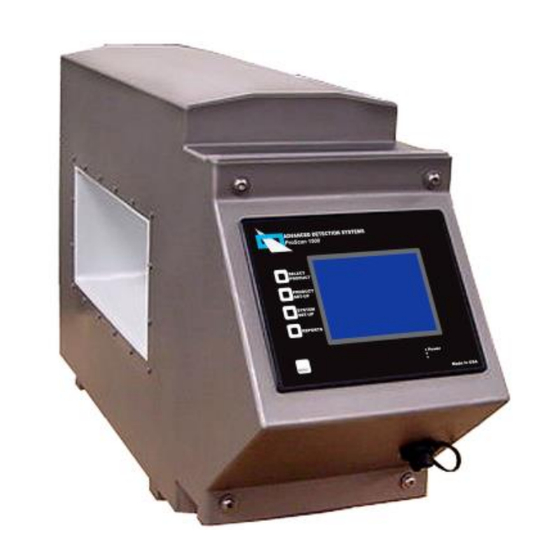
The ProScan Max II™ metal detector is a digital detector with a digital interface. All controls and adjustments are made with a touchscreen that also contains pushbutton shortcut keys. Product settings can be stored for quick line changeovers. -
Page 4: Installation Mechanical Installation
INSTALLATION MECHANICAL INSTALLATION The detector must be bolted securely in position, but do not twist or strain it in any way. Nothing should rest on the search head or touch the sides of it. If a conveyor is used, all feet must be firmly on the floor. The conveyor must not rock or move. Twisting of ... -
Page 5: Electrical Installation
ELECTRICAL INSTALLATION WARNING. Whenever wiring is to be done to the terminal strip of the detector, make sure ALL sources of power have been disconnected. Terminals controlling other devices may be powered from sources other than those supplying the metal detector. Caution should be used when working on machinery as components may stop and start automatically without warning. -
Page 6: Terminal Connections
TERMINAL CONNECTIONS WARNING: Whenever wiring is to be done to the terminal strip of the detector, make sure ALL sources of power have been disconnected. Terminals controlling other devices may be powered from sources other than those supplying the metal detector. Caution should be used when working on machinery as components may stop and start automatically without warning. -
Page 7: Explanation Of Terminal Connections
EXPLANATION OF TERMINAL CONNECTIONS TERMINAL DESCRIPTION TERMINAL DESCRIPTION RLY 5 Solid state relay output #5 AC +15 VDC IN Input power for the circuit board RLY 5 Solid state relay output #5 AC Input ground for the circuit board RLY 4 Solid state relay output #4 AC RLY1 COMM Common toggle for output relay #1 RLY 4... -
Page 8: Outputs For Reject And Signal Devices
Outputs For Reject and Signal Devices The detector has internal timing circuitry for the control of a variety of reject and alarm devices. Instructions for setting the reject delay and operate timing are given later in this manual. The solid state relay outputs 3, 4, and 5 are configurable as normally open or normally closed and can be changed by pressing Menu / Level 3 / Reject Options / Relay Config (See reject menu section for more details). -
Page 11: Front Panel Indicators
FRONT PANEL INDICATORS NAVIGATING THE MENU A "Menu Flow Chart" showing all of the possible command screens which can appear on the display would be very large and not practical to include in this manual. We've tried to simplify the menu system by making it very intuitive to follow the screens and buttons. -
Page 12: Security (Password)
When power is applied, the metal detector will sequence through a number of self-test screens, ending with the screen shown above. This screen is the “MAIN” screen, and it will appear on the display unless the user has entered one of the menu levels. The "MAIN" display shows which product number the metal detector is ready to inspect in the lower right hand corner. -
Page 13: Product Set-Up Procedures
PRODUCT SET-UP PROCEDURES SETTING THE DETECTOR TO COMPENSATE FOR PRODUCT EFFECT One of the basic principles that should be understood before adjusting the metal detector is product effect. Almost all products inspected are conductive to some degree, and create a signal, which is picked up by the metal detector. - Page 14 LEARN/RELEARN: Note, you must be logged in to level 2 or 3 in order to perform the learn function. Logging in on level 2 produces the following screen: Now press the “PRODUCT SET-UP” button to go to the learn menu. The following screen will appear: Now press the “LEARN/RELEARN”...
- Page 15 There are two types of learn processes, hand feed and automatic feed. Hand feed is used when there is a small sample of products that are not running continuously at the moment. They may be later during production. An example would be hams. The production line will run continuous hams, but you only have one. In this case you would select “HAND FEED”...
- Page 16 When the “PLEASE WAIT” screen goes off, place the product on the conveyor belt and allow it to pass through the detector aperture. If the product has enough signal, the “PLEASE WAIT” screen will appear again. When the detector has enough samples, the “LEARN SUCCESSFUL” screen will appear. The detector will usually require 2-3 passes of the product.
-
Page 17: Tips For Successful Auto-Learn
TIPS FOR SUCCESSFUL AUTO-LEARN Follow these hints to assure the best results when learning product: 1. Pick a sample product that is representative of products that will be run during production. 2. If products vary in size, pick the largest representative product. This will give you the "worst case" in background product signal. -
Page 18: Additional Items For Product Set-Up
ADDITIONAL ITEMS FOR PRODUCT SET-UP NAMING THE PRODUCT After the learn process has been completed, the operator should enter a name for the product. Name selection is available in level 2 or 3. At either menu select the “CHANGE PRODUCT NAME” button to go to the “PRODUCT NAMING MENU”. -
Page 19: Product Settings
PRODUCT SETTINGS A variety of settings are stored in the detector’s memory for each product. The product settings can be changed through the level 2 or 3 menus. To view the settings or to make changes go to MENU / LEVEL 2 / PASSWORD / PRODUCT SETTINGS. -
Page 20: Offset A
OFFSET A It is adjustable from 1-100 and is set during the learn process and should not need to be adjusted. OFFSET B OFFSET B is determined during the learn process and should not need to be adjusted. OFFSET C It is adjustable from 0-11 and is set during the learn process. -
Page 21: Product Tracking
PRODUCT TRACKING Product tracking is used when the product being inspected will slowly change during the course of a run. The change may be a gradual change in product temperature, moisture content, or mass. It is important to note that the change must be gradual. -
Page 22: Reject And Signal Devices Timing And Options
REJECT AND SIGNAL DEVICES TIMING AND OPTIONS A brief description of each reject term is shown below. The “REJECT OPTIONS” menu can be reached by MENU / LEVEL / PASSWORD / REJECT OPTIONS. Level 2 or 3 gives access to reject settings. The reject menu appears below. -
Page 23: Setting The Timing Of The Reject Device
Reject Mode Select - After metal has been detected the metal detector output can be delayed by timing circuits as described above. This works well for conveyor belts that move at a constant speed. In the case of variable speed drives or conveyors that stop and start occasionally another method of timing is preferred. A pulse counter circuit is the best alternative. - Page 24 4. Use a metal sample that is typical for the expected size of metal to be detected by a given metal detector width and height. The best samples to use are the test spheres that are shipped with the metal detector. If ferrous, nonferrous, and nonmagnetic stainless samples are on hand, use the ferrous test sample.
-
Page 25: Additional Features
ADDITIONAL FEATURES DATE/TIME SET-UP The metal detector has an internal "real-time" clock that keeps track of the current date and time. It is set at the factory and normally would not need to be adjusted. However, to compensate for different time zones and for changes in Daylight Savings Time, etc. -
Page 26: Performance Validation
PERFORMANCE VALIDATION The performance validation feature allows the use to set up periodic reminders that the product must be tested with the metal samples. When enabled, this feature reminds the user that performance validation is due. Access to the performance validation feature is through the ‘Reports’ hard key on the left. When pressed, the following screen appears: Select ‘Validation Menu’. - Page 27 Select ‘Validation Sample Size’ and the following screen will appear: Enter the size of the test wand you will be using during the test. This value will be saved in memory and listed on the data logger along with a time and date stamp upon successful completion of the ferrous test. Enter the desired values for each metal type.
- Page 28 Enter the desired shift start time, test interval and end time. Then, turn the validation reminder on. The performance validation reminder is now active. When the current time matches the test interval the following performance reminder screen will appear: Selecting ‘Cancel’ simply returns the system to the main screen. Selecting ‘Begin’ navigates the user back to the ‘Performance Validation Menu’...
-
Page 29: Troubleshooting
If the user desires more than a visual reminder that performance validation is due, an alarm contact can be connect to output relay 1 or 2. Those relay outputs are normally tied to the reject device, so the user must enable the performance validation alarm. -
Page 30: Intermittent False Trips
INTERMITTENT FALSE TRIPS Observe the surroundings. When the detector trips, try to figure out what could be causing it. Look for two pieces of metal making intermittent contact in the vicinity of the metal detector. Look for starting/stopping of nearby machinery. Verify that the electrical ground to the detector is making solid connection. -
Page 31: Adjusting Sweep Arm Reject Devices
SWEEP ARM ADJUSTMENT PROCEDURE FOR PROSCAN METAL DETECTOR EQUIPPED UNITS. Sweep arms are a commonly installed reject device on Advanced Detection Systems units. It is often necessary to adjust the sweep arm velocity beyond the standard factory settings. On the side of the conveyor frame, you will see an air regulator and control solenoid. -
Page 32: Transporting The Unit
These set screws should only be adjusted with the assistance of the factory. If you experience the sweep arm traveling too far, or not far enough, it may be necessary to adjust the range of motion, or stroke, of the arm. This is done by loosening the lock nut in the center of the cylinder and adjusting the large screw.
Need help?
Do you have a question about the ProScan Max II and is the answer not in the manual?
Questions and answers