Advertisement
Advertisement
Table of Contents

Subscribe to Our Youtube Channel
Related Manuals for IECHO PK-0604

Summary of Contents for IECHO PK-0604
- Page 1 PK User's Manual Hangzhou IECHO Science & Technology Co.,LTD.
-
Page 2: Working Principles
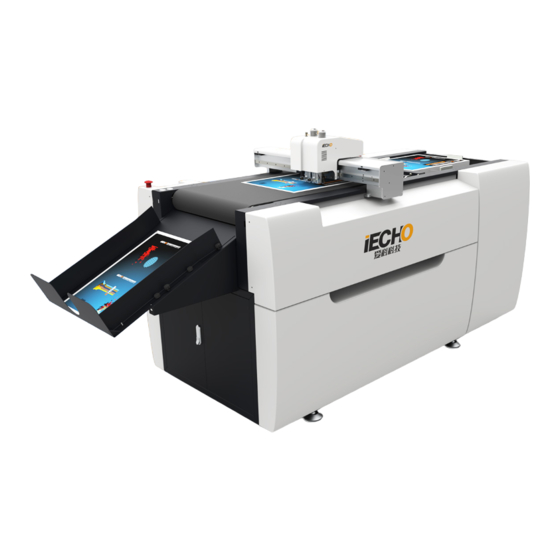
FOREWORD PK automatic intelligent cutting system adopts fully automatic vacuum chuck, automatic lifting and feeding platform. Equipped with various of tools, it can quickly and precisely make through cutting, half cutting and creasing. It is suitable for sample making and short-run customized production for Signs, Printing and Packaging industries. It is a cost-effective smart equipment that meets all your creative processing. -
Page 3: Technical Parameters
1. Technical Parameters Machine model PK-0604 Conveyor system Vacuum chuck Material dimension 600mm x 400mm Tools Universal Cutting Tool, Creasing Tool, Kiss-cut Tool, Oscillating Tool Max cutting speed 1000mm/s Cutting thickness ≤6mm Accuracy 0.1mm DXF、PLT、PDF、HPG、HPGL、TSK、BRG、XML、CUT、OXF、ISO、AI、 File format PS、EPS Interface USB Port 220v±10%50HZ... - Page 4 1.1 PK Direction Information front right back X-axis left Y-axis...
-
Page 5: List Of Tools
1.2 List of tools Image Description Activity Various Allen keys (SW 1.5 to 8) Various open-ended spanners (SW 5.5-19.2x10) Various Phillips and slotted screwdrivers Precision spirit level To level the machine foot Electric drill Side cutters To open the transport locking devices Measuring tape... - Page 6 2. Preconditions 2.1 Installation location Make sure that the following requirements are met: The installation location is level and can withstand the floor loads. • The shipping crates can be deposited close to the installation location and their presence • does not prevent the machine from being assembled.
-
Page 7: Installation
Only complete the installation when all parts are present and undamaged. • • Inform IECHO customer service if any parts are missing or damaged. Replenish or replace missing or damaged parts. • Remove all screws on the upper side of the packing crate. - Page 8 3.2 Initial leveling of the base frame Lift each side support end to keep the balance by precision spirit level. Determine the basic position of one foot and adjust the height of other machine feet according to the basic position. Finally, to make all feet are at the same level.
- Page 9 3.3 Installing collection device A Install the collection device at the specified location. B The angle of collection device can be adjusted depending on the size of the material.
- Page 10 3.4 Air supply connection. Open the cover, and the air compressor is placed under the table. The diameter of air tube is 8mm.
- Page 11 Power installation Vacuum pump, machine and PC : all come with single-phase three-wires electronic control system. 3.5.1 Connect the static device...
- Page 12 3.5.2 Power input and other connector information AC220V Input Connector of static device Connector of power strip USB port for CCD camera Connector of air compressor PC Comm...
- Page 13 3.5.3 Connect the PC or laptop to the cutter...
- Page 14 4. Safety device on the machine and main switches Main switch Emergency stop switch Pause switch...
- Page 15 5. Feeding system for sheet materials 5.1 Put the materials on the specified position, and then adjust blocking plates.
- Page 16 5.2 Adjust the placement of material meet the following requirements: 1. According to the position of the suction plate, adjust the position of materials to achieve the best adsorption effect. 2. The edge of materials should be aligned with the edge of the loader.
-
Page 17: Module Information
6. Module information PK digital cutter including 4 type tools : TW1, TW2, Crease, EOT (optional) TW 1 TW 2 Crease CCD Camera EOT Material Pressing Tray... - Page 18 6.1 Tools installation 6.1.1 TW1 / TW2 tool Install the blade to the TW1/TW2 (Picture 1.2). • Insert the TW1/TW2 into the module, rotate the clamp clockwise to tight(Picture 3.4). • Adjust the knife height by screwing A or B. When the knife point touches the felt surface, •...
- Page 19 6.1.2 Crease tool Put the wheel part in the slot of holder (Picture 1.2). • Confirm the crease tool is in proper place of holder, then tighten the screw (Picture 3). • Rotate the retaining ring for adjusting the crease tool height. Anti-clockwise rotate, the crease •...
- Page 20 6.1.3 EOT tool Remove the EOT material pressing tray, anti-clockwise screw from the module (Picture 1). Insert the blade into the shim, and confirm the blade part is into proper position of holder, • and then tighten the screw (Picture 2. 3). Rotate the retaining ring for adjust the EOT tool height.
- Page 21 7. Circuit board and motor driver X driver EPOS board Y driver DSP board Z driver...
- Page 22 Put the materials on the table, start the vacuum pump, which make the materials to be adsorbed on the table. Open “IECHO Digital cutting system”, import the files (DXF or PLT). The system will process the analysis of ...
-
Page 23: Maintenance
9. Maintenance Check all the sockets of power, as well as the connector of serial cable. Before cutting, make X/Y running slower, then check whether has abnormal sound. Without cutting, start the tools, check whether the tools are workable. Clean everything after finishing the jobs. - Page 24 Clean both side of X. Y rail and EOT transmission. Add lubricating oil to feeding system.
-
Page 25: Safety Attentions
This manual copyright belongs to Hangzhou IECHO Science & Technology Co., LTD (hereinafter referred to as IECHO) IECHO will not make any guarantee for this manual, IECHO will not be responsible for this user manual when cause the misunderstanding.
Need help?
Do you have a question about the PK-0604 and is the answer not in the manual?
Questions and answers