Table of Contents
Advertisement
Quick Links
EXW1-TF222-092EN-A
ORIGINAL INSTRUCTIONS
Instruction Manual
SMC Wireless Adaptor
Series EXW1-A11N-X1
The intended use of this product is to provide a wireless communication
between wireless adaptors via a wired connection using Air Management
Hub.
1 Safety Instructions
These safety instructions are intended to prevent hazardous situations
and/or equipment damage. These instructions indicate the level of
potential hazard with the labels of "Caution," "Warning" or "Danger."
They are all important notes for safety and must be followed in addition
to International Standards (ISO/IEC)
*1)
, and other safety regulations.
*1)
ISO 4414: Pneumatic fluid power - General rules relating to systems.
ISO 4413: Hydraulic fluid power - General rules relating to systems.
IEC 60204-1: Safety of machinery - Electrical equipment of machines.
(Part 1: General requirements)
ISO 10218-1: Manipulating industrial robots -Safety. etc.
• Refer to product catalogue, Operation Manual and Handling
Precautions for SMC Products for additional information.
• Keep this manual in a safe place for future reference.
Caution indicates a hazard with a low level of risk which, if
Caution
not avoided, could result in minor or moderate injury.
Warning indicates a hazard with a medium level of risk
Warning
which, if not avoided, could result in death or serious injury.
Danger indicates a hazard with a high level of risk which, if
Danger
not avoided, will result in death or serious injury.
Warning
• Always ensure compliance with relevant safety laws and
standards.
All work must be carried out in a safe manner by a qualified person in
compliance with applicable national regulations.
2 Specifications
2.1 General specifications
Item
Specification
Enclosure rating
IP67
Ambient operating temperature
-10 to +50
°
C
Ambient storage temperature
-20 to +60
°
C
Ambient humidity
35 to 85% RH (no condensation)
500 VAC for 1 minute between
Withstand voltage
external terminals (including the FE
terminal) and enclosure screws
10 MΩ or more (500 VDC between
Insulation resistance
external terminals (including the FE
terminal) and enclosure screws
EN61131-2 compliant:
Vibration resistance
5 ≤ f < 8.4 Hz 3.5 mm
8.4 ≤ f < 150 Hz 9.8 m/s
EN61131-2 compliant:
Impact resistance
147 m/s
2
, 11 ms
Weight
30 g
2 Specifications (continued)
2.2 Electrical specifications
Item
Power supply voltage for
12 VDC -10% to 24 VDC +10%
control
Current consumption
2.3 Wireless Communication specifications
Item
Specifications
SMC original protocol
Protocol
(SMC encryption)
Frequency Hopping Spread Spectrum
Radio wave type (spread)
Frequency band
2.4 GHz (2403 to 2481 MHz)
Frequency channels
79 ch (Bandwidth: 1.0 MHz)
Communication speed
Up to 100 m line of sight
Communication distance
(Depends on the environment)
Radio Law certificates
Refer to the operation manual.
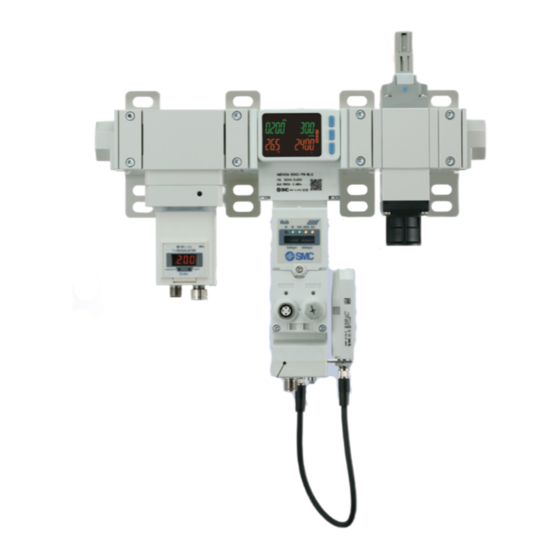
3 Name and Function of parts
• Wireless Adaptor
No.
Item
M8 connector for cable to wireless
1
Connector
base or remote.
2
Nut
For fixing to Air Management Hub.
3
LED display
Indicates the status of the adaptor.
2
4 Installation
4.1 Installation
Specification
• Do not install the product unless the safety instructions have been read
and understood.
50 mA or less
4.2 Mounting
Mount the wireless adaptor bracket to the Air Management Hub using the
screw attached to the Air Management Hub. (Recommended torque: 0.3
±10% N•m). Then attach the cable EXW1-AC1-X1 to the wireless adaptor
and Air Management Hub. (When inserting the cable into the Wireless
adaptor, use an insertion force of 10 N or less).
(FHSS)
1 Mbps
Mount the adaptor to the bracket of the Air Management Hub using the
M10 nut already installed to the wireless adaptor (Recommended torque:
0.9 ±10% N•m).
Description
4 Installation (continued)
4.3 Environment
Warning
• Do not use in an environment where corrosive gases, chemicals, salt
water or steam are present.
• Do not use in an explosive atmosphere.
• Do not expose to direct sunlight. Use a suitable protective cover.
• Do not install in a location subject to vibration or impact in excess of
the product's specifications.
• Do not mount in a location exposed to radiant heat that would result in
temperatures in excess of the product's specifications.
5 Wiring
5.1 Wiring Connections
• Connector
No.
1
2
Internal Bus B
3
4
Internal Bus A
• The EXW1-AC1-X1 is the cable which should be used for connection
to the Air Management Hub.
Radio laws require cables to be less than 3 m long, shielded and
twisted pairs.
6 LED Display
• The LED indicators on the wireless adaptor indicate the power supply,
communication and diagnostic status.
LED
LED Colour
Green LED
PWR
Red LED ON Unrecoverable error is detected.
Green LED
Green LED
flashing
(1 Hz)
W-SS
Green LED
flashing
(2 Hz)
Red LED
flashing
Warning
M8, 4-pin, plug
Signal
A-coded
24 V (US1)
0 V (US1)
Caution
Operation
US1 (for control) power supply is ON
ON
OFF
US1 (for control) power supply is OFF
The level of received radio wave power is 3.
ON
The level of received radio wave power is 2.
The level of received radio wave power is 1.
No Remotes are connected.
OFF
Wireless Base or Remote is not registered.
Page 1 of 2
Advertisement
Table of Contents

Related Manuals for SMC Networks EXW1-A11N-X1 Series


Summary of Contents for SMC Networks EXW1-A11N-X1 Series
- Page 1 EXW1-TF222-092EN-A 2 Specifications (continued) 4 Installation 4 Installation (continued) ORIGINAL INSTRUCTIONS 4.1 Installation 2.2 Electrical specifications 4.3 Environment Warning Warning Item Specification Instruction Manual • Do not install the product unless the safety instructions have been read Power supply voltage for •...
- Page 2 EXW1-TF222-092EN-A 7 How to Order To obtain information about this product, please contact SMC. 8 Outline Dimensions (mm) To obtain information about this product, please contact SMC. 9 Maintenance 9.1 General Maintenance Caution • Not following proper maintenance procedures could cause the product to malfunction and lead to equipment damage.
Need help?
Do you have a question about the EXW1-A11N-X1 Series and is the answer not in the manual?
Questions and answers