Table of Contents
Advertisement
Advertisement
Table of Contents

Related Manuals for EARDATEK KINGSAT KM-V3


Summary of Contents for EARDATEK KINGSAT KM-V3
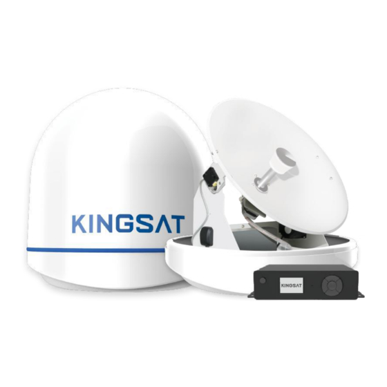
- Page 1 KINGSAT Satellite TV Antenna System www.kingsat-tech.com sales@kingsat-tech.com...
-
Page 2: Table Of Contents
KINGSAT Satellite TV Antenna System Table of Contents 1. INTRODUCTION ..................3 1.1 Introduction to KINGSAT KM-V3/V4/V6/V7 ......... 3 1.2 Features of KINGSAT KM-V3/V4/V6/V7 ........3 2. INSTALLATION ..................5 2.1 Preparation ................... 5 2.2 Planning the Installation ............... 6 2.3 Installation and Mounting of Antenna ......... -
Page 3: Introduction
KINGSAT Satellite TV Antenna System 1. INTRODUCTION 1.1 Introduction to KINGSAT KM-V3/V4/V6/V7 KINGSAT KM-V3/V4/V6/V7 is a digital satellite antenna system. It’s designed for all types of vessels to automatically search, track and capture satellite signal from the Digital Video Broadcasting (DVB) compatible satellites. - Page 4 KINGSAT Satellite TV Antenna System Strong Signal Receiving performance Using self-made LNB and RF processing components, which offers the best reception quality and maximum antenna performance. Fast Satellite Search and Position An integrated GPS antenna allows for the antenna control system to update the GPS data automatically for accurate positioning and faster satellite locking.
-
Page 5: Installation
KINGSAT Satellite TV Antenna System 2. INSTALLATION 2.1 Preparation Standard components Antenna Unit*1 Antenna Control Unit(ACU)*1 24V/3A Adapter for ACU*1 Hex head bolt , Spring washer , Flat washer , Nut , Mounting bracket , Tapping screw Cables: 15-meter coaxial cable * 2 Power cable*1 *M8 is applicable on V3/V4/V6, M12 is applicable on V7. -
Page 6: Planning The Installation
KINGSAT Satellite TV Antenna System 2.2 Planning the Installation Antenna Unit Install the antenna in accordance with the following procedures to ensure maximum performance of the antenna. The antenna must be installed at the position: (1) It has an all-around clear view of the horizon. (2) There are no obstacles within 1 degree above the antenna. -
Page 7: Installation And Mounting Of Antenna
KINGSAT Satellite TV Antenna System Cables Cables must be routed correctly. Before installing the system cables, consider the following points: (1) All cables need to be well clamped and protected from physical damage and exposure to heat and humidity. (2) Do not bend cables excessively. (3) Where a cable passes through an exposed bulkhead or deck head, a watertight grommet or swan neck tube should be used. - Page 8 KINGSAT Satellite TV Antenna System Figure 5.1: Radome Dimension of KM-V3 Figure 5.2: Radome Dimension of KM-V4 Figure 5.3: Radome Dimension of KM-V6 Figure 5.4: Radome Dimension of KM-V7...
- Page 9 KINGSAT Satellite TV Antenna System Confirming of the Antenna Mounting Position Referring to the mounting template, mark where antenna will be mounted on board (it must be a flat surface) or on a separate power tower. Note: Exposed cable must be protected because an exposed cable may cause electric shock and cause serious damage to the equipment.
- Page 10 KINGSAT Satellite TV Antenna System Connection of the Cable Remove the rubber cap from RF connector. Connect the RF cable to the RF connector at the bottom of the base plate through the access hole using an adjustable spanner. Be careful not to over tighten and damage the connector. Figure 7: Connectors on Bottom of Antenna Note: Do not tighten excessively when using the spanner, it will damage the threads.
- Page 11 KINGSAT Satellite TV Antenna System Mounting the Antenna Attach the antenna by using the hex head bolts, spring washers, flat washers and nut supplied. There are two different ways for different models: Figure 8.1: Mounting the Antenna Figure 8.2: Mounting the Antenna *M8 is applicable on V3/V4/V6, M12 is applicable on V7.
-
Page 12: Installing The Acu
KINGSAT Satellite TV Antenna System 2.4 Installing the ACU ACU Dimension Figure 9: Dimension of ACU Select ACU Installation Site The ACU should be installed below desk, in a location that is: (1) Dry, cool and ventilated. (2) Easy accessed from your main TV viewing area. - Page 13 KINGSAT Satellite TV Antenna System Installing the ACU (1) The ACU should be installed using the two supplied mounting brackets which are allowed for a top or bottom mounting configuration. (2) Using the self-tapping screws supplied, attach the mounting brackets to both sides of the ACU.
- Page 14 KINGSAT Satellite TV Antenna System Connecting the System Cables of KM-V3/V4/V6/V7 After installing and mounting the antenna, connect the ACU to the antenna. Refer to the drawing shown below to connect cables. Cable Connection (1) Connect “RF1” on the antenna base plate to “ANT-RF1” on the ACU. (2) Connect “RF2”...
- Page 15 KINGSAT Satellite TV Antenna System Multi-Receivers Solution In order to connect multi-Receivers to the antenna, you need to purchase a suitable Multi Switch. The Multi Switch has to be installed between the antenna until and the Receivers as shown in the following diagram. *Multi Switch and STBs are not included in the standard package Figure 13: Multi-Receivers Solution...
-
Page 16: Operation Instruction
KINGSAT Satellite TV Antenna System 3. OPERATION INSTRUCTION 3.1 Introduction This section of the Manual describes how to setup your Satellite TV System using the ACU. It includes the following functions: Note: Many of the above functions will only be required after first installation of your system. -
Page 17: Operating The Acu
KINGSAT Satellite TV Antenna System 3.2 Operating the ACU ACU Soft Keys Figure 14: ACU Soft Keys... - Page 18 KINGSAT Satellite TV Antenna System NORMAL MODE 1. START UP With the system installed and power applied, the ACU screen will show the following sequences: 1. Press POWER and the brand will be shown on MONITOR. 2. Data communication is being established between the antenna and the ACU.
- Page 19 KINGSAT Satellite TV Antenna System 3. CHANGE TARGET SATELLITE The antenna is pre-programmed with up to 6 satellites as default mode. You can change your target satellite easily and the antenna will track it automatically. 1. On homepage, press OK to enter SATELLITE SELECT mode. 2.
- Page 20 KINGSAT Satellite TV Antenna System SETUP MODE 1. SET SAT LIST You can change the Pre-programmed satellites. 1. On homepage, press RIGHT ► to enter SETUP MODE. Select SET SAT LIST and press OK. Set SAT 1: Select SAT 1 and press OK. Then you can press LEFT ◄...
- Page 21 KINGSAT Satellite TV Antenna System 2. SET LNB INFO You may set the LNB information in this mode. But it is not recommended for a novice satellite service user to use this mode. 1. Select SET LNB INFO and press OK. 2.
- Page 22 KINGSAT Satellite TV Antenna System 3. SET GPS It is possible to set up and modify the GPS information, which enhances the antenna functionality and positioning performance. 1. Select SET GPS and press OK. 2. Select LONGITUDE and press OK to modify the value of longitude. UP ▲...
- Page 23 KINGSAT Satellite TV Antenna System 4. EDIT SATELLITE INFO It is possible to modify the existing satellite information and input new satellite information into the ACU as well. It is not recommended to setup in this mode for a user who is unwell-known of satellite parameter. 1.
- Page 24 KINGSAT Satellite TV Antenna System 7. Select the Voltage Supply Method to LNB. 18V-Hor/L --- This item means LNB voltage is selected with 18V, and matched polarization is that Linear- Horizontal, Circular -Left; 13V-Ver/R --- This item means LNB voltage is selected with 13V, and matched polarization is that Linear- Vertical, Circular -Right;...
- Page 25 KINGSAT Satellite TV Antenna System 5. ACU DiSEqC 1.0 Function(Additional version) KINGSAT ACU with additional version can support DiSEqC 1.0 which is protocol between receiver and ACU that easily switch 1-4 satellite from receiver DiSEqC 1.0 command. Before setup, ACU Satellite list must be lined up by 1-4 which are matched with DiSEqC 1.0 port1-port 4 from receiver.
- Page 26 KINGSAT Satellite TV Antenna System 6. SET TO DEFAULT It is possible to reset all the parameters back to the default setting in this mode. 1. Select SET TO DEFAULT and press OK. 2. Press YES to reset all the parameters to default. Press NO to cancel resetting to default.
- Page 27 KINGSAT Satellite TV Antenna System MONITOR/DIAGNOIST The antenna status can be checked by viewing the results of the diagnostic self-test of the antenna. Refer to the following codes to understand the test results. 1. On homepage, press RIGHT► twice continuously to enter MONITOR/DIAGNOST mode.
-
Page 28: Error Code And Solutions
KINGSAT Satellite TV Antenna System 3.3 Error Code and Solutions E01 The initialization of Antenna control board failed E02 Antenna Input Power is tested. If failed, check the RF cable. E03 Skew System is tested. If Failed, check the control board, skew motor. E04 Tuner is tested. -
Page 29: Preparation For Transportation
(4) Cover upper part of radome. Be careful not to touch the reflector when assembling upper part of radome. (5) Pack KINGSAT KM-V3/V4/V6/V7 into the original package box. Plastic foam Plastic foam...
Need help?
Do you have a question about the KINGSAT KM-V3 and is the answer not in the manual?
Questions and answers