Table of Contents
Advertisement
Quick Links
Advertisement
Table of Contents

Related Manuals for EARDATEK KINGSAT Maritime VSAT P8


Summary of Contents for EARDATEK KINGSAT Maritime VSAT P8
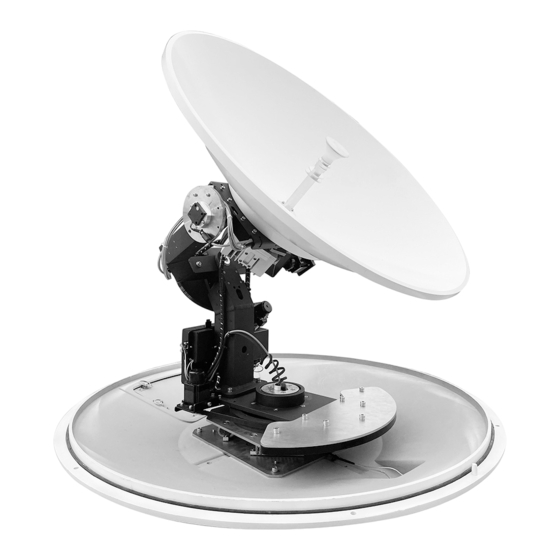
- Page 1 Quick Installation Maritime VSAT P8/P8+ Standard Version 2.1...
-
Page 2: Table Of Contents
Contents www.eardatek.com Preparation for Installation Antenna First Installation Checklist Part 1 Antenna Installation Site (ADU Preparation) Part 2 ACU and Modem (BDU Preparation) Installation Step 1 Mounting Antenna Step 2 Connection Diagram Step 3 Confirm All Connections Step 4 ACU Setting Procedure... -
Page 3: Antenna First Installation Checklist
Preparation for Installation Antenna First Installation Checklist www.eardatek.com For the first installation, please follow the steps below. Check each step to ensure that the antenna is installed and used correctly.Each step after well done with mark "√". Part1 Antenna Installation Site (Above Deck Unit Preparation) Attention: Keep safe distance for radiation hazard. -
Page 4: Part 1 Antenna Installation Site (Adu Preparation)
Preparation for Installation Part-1 Antenna Installation Site (ADU Preparation) www.eardatek.com Step 1.Attention: When VSAT working especially transmitting signal, make sure 100% keep safe distance (15m far from ADU ) for radiation hazard. Radiation Hazard Area No nearing 10° 10° Safety Warning... - Page 5 Preparation for Installation Part-1 Antenna Installation Site (ADU Preparation) www.eardatek.com Step 2. Check if any obstructions exist with EL range -15°~120°. Make sure antenna is free of obstructions ,it can transmit and receive the satellite signal fully. The Optimized site is that 360° free of obstruction when pointing to sky.
- Page 6 Preparation for Installation Part-1 Antenna Installation Site (ADU Preparation) www.eardatek.com Step 3.Check mounting mast site. The optimized site has (1)Minimum vibration (better far from engine) (2)Keep safe distance to Radar or other RF transmitter (aviod fan beam ±15°of Radar, keep distance to...
- Page 7 Preparation for Installation Part-1 Antenna Installation Site (ADU Preparation) www.eardatek.com Step 4.Check physical solidness of mast. Make sure the mast has (1)Enough height ,must be free of obstructions. (2)Good flatness, plateau is below (3)High solidness, it can withstand 80kg. Mast can...
- Page 8 Preparation for Installation Part-1 Antenna Installation Site (ADU Preparation) www.eardatek.com Installation Site Selection and Case Analysis The optimal sites The following installation cases are the optimal sites.
- Page 9 Preparation for Installation Part-1 Antenna Installation Site (ADU Preparation) www.eardatek.com Installation Site Selection and Case Analysis Can be optimized The following installation cases are not the optimal sites and can be optimized. Too close to the mast, the antenna may be obstructed at mast direction.
- Page 10 Preparation for Installation Part-1 Antenna Installation Site (ADU Preparation) www.eardatek.com Installation Site Selection and Case Analysis Must be optimized The following installation cases are not the optimal sites and must be optimized. Too close to the mast, antenna can not get 360° free view to sky.
- Page 11 Preparation for Installation Part-1 Antenna Installation Site (ADU Preparation) www.eardatek.com Step 5.1: Unpack carton and take out the accessories.Remove the fixing screw on the radome bracket that secures the antenna to the pallet using a wrench.
- Page 12 Preparation for Installation Part-1 Antenna Installation Site (ADU Preparation) www.eardatek.com Step 5.2: The antenna comes with the lifting straps pre-mounted from the factory. Take out the shackle from the bottom of the lifting straps and unscrew it.
- Page 13 Preparation for Installation Part-1 Antenna Installation Site (ADU Preparation) www.eardatek.com Step 5.3 Remove radome. Then remove 4 red fixing bolts of safe delivery purpose. After that, fix the radome with bolts, put back the lifting straps, and tighten up the shackle.
- Page 14 Preparation for Installation Part-1 Antenna Installation Site (ADU Preparation) www.eardatek.com Step 6.Check Material List in the carton.
- Page 15 Preparation for Installation Part-1 Antenna Installation Site (ADU Preparation) www.eardatek.com Step 7.Check connecting cables. We supply below accessories for each unit of antenna. 2 * 15 meter coaxial cable (RG6 black color) 2 * 1 meter coaxial cable (RG179 gold color)...
- Page 16 Preparation for Installation Part-1 Antenna Installation Site (ADU Preparation) www.eardatek.com Step 8.Check connecting diagram. coaxial cable 15M with RG6 coaxial cable 1M with RG179 network cable with RJ45 plugs If the supplied coaxial cable 15m with VSAT P8/P8+ Antenna RG6 can not meet requirement , We...
-
Page 17: Part 2 Acu And Modem (Bdu Preparation)
Preparation for Installation Part-2 ACU and Modem (BDU Preparation) www.eardatek.com Step 9.Check ACU. Check each port of rear panel connection. Front Panel of ACU USB port,for Indicators, show 256x64 OLED display, Buttons for ACU operation upgrading antenna shows all status and firmware of ACU... - Page 18 Preparation for Installation Part-2 ACU and Modem (BDU Preparation) www.eardatek.com Step 10.Check connections of ACU , Modem and Switch. coaxial cable 15M with RG6 coaxial cable 1M with RG179 network cable with RJ45 plugs e.g.Router e.g.IP Cam e.g.VoIP Antenna Control Unit...
-
Page 19: Installation
Installation Step 1 Mounting Antenna www.eardatek.com Check the condition of the lifting strap and that the shackle is tightened up. Lift the antenna above the mast using a crane and carefully put the antenna down on the mast. Mounting antenna with below accessories. -
Page 20: Step 2 Connection Diagram
Installation Step 2 Connection Diagram www.eardatek.com Prepare cables and make sure connections as below diagram. Supplied cables 2 * 15 meter coaxial cable (RG6 black color) 2 * 1 meter coaxial cable (RG179 gold color) 2 * 0.4 meter network cable with RJ45 plugs... -
Page 21: Step 3 Confirm All Connections
Installation Step 3 Confirm All Connections www.eardatek.com Review all connections. Antenna connections ACU connections Connectors should be sealed with waterproof tape Modem connections... -
Page 22: Step 4 Acu Setting Procedure
Installation Step 4 ACU Setting Procedure www.eardatek.com Turn on power of the ACU. ACU starts to initialize. Error may happen as below shows. This means ACU can not communicate with antenna correctly. Please check all cable connections(whether the TX and RX coaxial cables are connected wrongly, or whether the F-N RF heads are tight) and restart system. -
Page 23: Step 5 Antenna Operating Status
Installation Step 5 Antenna Operating Status www.eardatek.com After initialization, the antenna GPS module successfully obtains longitude and latitude, and the GPS icon appears as shown in the figure below. At the same time, the MODEM communicates with the antenna controller ACU, and the OPENAMIP icon flashes. -
Page 24: Step 6 Satellite Locking
Installation Step 6 Satellite Locking www.eardatek.com When the antenna lock the satellite successfully, the parameter information and tracking status “TRACKING” will be shown on display. Now VSAT antenna is working correctly and tracking satellite as requirement. Press UP button to display all MODEM status information. -
Page 25: Step 7 Testing Internet Link
Installation Step 7 Testing Internet Link www.eardatek.com Connect to the PC and test whether the Internet link is connected successfully. coaxial cable 15M with RG6(supplied) coaxial cable 1M with RG179(supplied) network cable with RJ45 plugs(supplied) e.g.Router e.g.IP Cam Antenna Control Unit... -
Page 26: Step 8 Setting Done And Surf Internet
Installation Step 8 Setting Done and Surf Internet www.eardatek.com Now you can connect all IP devices to LAN ports of ACU ,then surf internet. coaxial cable 15M with RG6(supplied) coaxial cable 1M with RG179(supplied) network cable with RJ45 plugs(supplied) e.g.Router e.g.IP Cam... - Page 27 Installation Step 8 Setting Done and Surf Internet www.eardatek.com Connect as shown in the figure below, if user needs to access VOIP phones with VLAN settings. coaxial cable 15M with RG6(supplied) coaxial cable 1M with RG179(supplied) network cable with RJ45 plugs(supplied)
-
Page 28: 1-Antenna Status Monitor- View Mode Of Acu
Appendix 1 Antenna Status Monitor- View Mode of ACU www.eardatek.com View1_RX View2_IP View Mode press “ ” button on ACU View3_TX View4_Status View5_Version Lock1_DVB Lock2_AGC Setup1_Lock Mode ACU Main Menu Lock3_Modem Lock4_Beacon Setup2_IP IPSetting Sat Setting Set1_SAT INFO Set2_LNB LNB Setting... - Page 29 Appendix 1 Antenna Status Monitor- View Mode of ACU www.eardatek.com Main display description: OPENAMIP icon,Modem communicating with ACU,only show in MODEM mode Current lock mode: GPS locating DVB, AGC, MOD,BEA successfully Current date and time Longitude of satellite Current status of the antenna(ADU): Strength and quality of signal 1.Init.: Antenna initializing...
- Page 30 Appendix 1 Antenna Status Monitor- View Mode of ACU www.eardatek.com View display description:Press the right button of the ACU to display the following pages page by page. Internet Protocol address. Longitude of selected satellite. Longitude of satellite BC_FRQ Beacon frequency of selected satellite.
- Page 31 Appendix 1 Antenna Status Monitor- View Mode of ACU www.eardatek.com ACU Software Outline View1_RX View2_IP View Mode View3_TX View4_Status View5_Version Lock1_DVB Lock2_AGC Setup1_Lock Mode ACU Main Menu Lock3_Modem Lock4_Beacon Setup2_IP IPSetting Sat Setting Set1_SAT INFO Set2_LNB LNB Setting Setup3_Parameter Set3_GPS...
-
Page 32: 2-Upgrade
Appendix 2 Upgrade www.eardatek.com Reflector TX to BUC TX with DC 24V Feed-horn Board RX + 13/18V Part 2 Upgrade ADU for P series VSAT Main Board Main Gyro SK MOTOR GNSS Sensor SlipRing BLDC Drivers EL Gyro Sensor DC 48V... - Page 33 Appendix 2 Upgrade www.eardatek.com Part 1 Upgrade BDU for P series Normally latest version of ACU firmware is needed, plz follow below steps to upgrade it. Step 1. Get the up-to-date firmware from KINGSAT or official distributor. Step 2. Copy the firmware to USB flash disk and ensure it is at root directory;...
- Page 34 Appendix 2 Upgrade www.eardatek.com Part 2 Upgrade ADU for P series 1.Download and install app ” RemoteWriter” on one Android phone from official distributor. 2.At Setup Mode, select<6. SET OTHERS> then turn on WIFI.
- Page 35 Appendix 2 Upgrade www.eardatek.com Part 2 Upgrade ADU for P series 3. Open the Android phone application "Remote Writer", make sure there is a network connection (4G/wifi) , wait for a few seconds, from "Updating Resources" until "Successful Resource Acquisition" is displayed.The download of the latest firmware from the server is complete.
- Page 36 Appendix 2 Upgrade www.eardatek.com Part 2 Upgrade ADU for P series 5. Return to the "Remote Writer" application, enter the firmware list, and confirm the firmware version of the current device. 6. Select the appropriate firmware version and click the up icon to upgrade.
-
Page 37: 3-Troubleshooting Guide
Appendix 3 Troubleshooting Guide www.eardatek.com Error Code and Solutions E01. The initialization of antenna mainboard failed, please check connections of Tx and Rx cables and N-F connectors also check the antenna mainboard. E02. The detection of antenna power failed, please check connections of Tx and Rx cables and N-F connectors. - Page 38 Appendix 3 Troubleshooting Guide www.eardatek.com Elevation motor issue. Check if the RF cable Gyro sensor issue. Check if EL motor is stuck between LNB and mainboard is Check if the connection of sensor is loose. or belt of EL motor is loose or broken.If not, replace...
- Page 39 Appendix 3 Troubleshooting Guide www.eardatek.com Skew motor issue. Check if SK motor is stuck, or belt of Azimuth motor issue. SK motor is broken or the connector Check if AZ motor is stuck of polarization switch is loose. or belt of AZ motor is broken.
- Page 40 Appendix 3 Troubleshooting Guide www.eardatek.com Check if cable of cross level motor and connector is loose. Check if the connector of gyro sensor is loose. Check if cable of elevation motor and limit sensor connectors are loose. Check if cable of azimuth motor and Check if cable of skew motor and limit sensor connectors are loose.
- Page 41 Appendix 3 Troubleshooting Guide www.eardatek.com If the SATCOM link broken, it may come from below reasons ( Factors effect link stability) A.Hardware issue. The antenna may miss pointing or have B.Installation issue. If the installation site is not optimal, tracking error, it may come from wrong configuration of...
- Page 42 Appendix 3 Troubleshooting Guide www.eardatek.com If the SATCOM link broken, it may come from below reasons ( Factors effect link stability) E.Interference issue. If not installed with safe distance from RF F.Weather issue. The rain attenuation, caused by source like radar ,VHF Tx antenna, GPS , AIS ,etc., VSAT antenna rain or thick clouds at the location of the antenna will get bad reception effected by RF interference.
- Page 43 Appendix 3 Troubleshooting Guide www.eardatek.com Basic information confirmation 1. Confirm the GPS icon and OPENAMIP icon appeared on the main page of the ACU Make sure that the GPS icon and OPENAMIP icon appear correctly. At the same time, if the GPS module works properly, longitude and latitude and the time must be correct.
- Page 44 Appendix 3 Troubleshooting Guide www.eardatek.com Basic information confirmation 2. Confirm the antenna status displayed on the ACU View Press the right button of the ACU to enter ACU View mode to see the overall state of the antenna. First confirm that the antenna is in MOD mode.
- Page 45 Appendix 3 Troubleshooting Guide www.eardatek.com Basic information confirmation 3. Confirm the MODEM baudRate Confirm that the ACU console and MODEM console port are connected with a network cable, and then Press OK --- SET PARAM --- 6. SET CONSOLE PORT --- BaudRate, here set the BaudRate.
- Page 46 Appendix 3 Troubleshooting Guide www.eardatek.com Basic information confirmation 4. View the MODEM status Press UP button to display all MODEM status information. The SN is the serial number of the MODEM. This is a unique identifier for VSAT terminal. This SN number is required for all kinds of business with the hub station NOC.
- Page 47 Appendix 3 Troubleshooting Guide www.eardatek.com Basic information confirmation 5.1 Switch to TVRO System to confirm the SATCOM link a.Press BACK button for three seconds, and the prompt "Switch to TVRO System" appears to switch the TVRO mode. The following picture appears, which means that the TVRO mode has been switched to.
- Page 48 Appendix 3 Troubleshooting Guide www.eardatek.com Basic information confirmation 5.2 Satellite parameters query in TVRO mode Click the website ( http://www.lyngsat.com) to find the satellite used locally, confirm the Ku satellite and the frequency with TV program, and record the satellite, frequency, symbol rate and polarization.
- Page 49 Appendix 3 Troubleshooting Guide www.eardatek.com Basic information confirmation 6. Manual search to confirm the SATCOM link a. Download and install app "Dish Align" or similar SAT finder application.
- Page 50 Appendix 3 Troubleshooting Guide www.eardatek.com Basic information confirmation b. Use the SAT finder application to confirm the automatic alignment direction of the antenna. Step 1. Positioning Step 3. Move the phone 360° t Step 4. Confirm whether the automatic Step 2. Select the target satellite o find the strongest signal...
- Page 51 Appendix 3 Troubleshooting Guide www.eardatek.com Basic information confirmation If the direction of antenna pointing is not matched with "Dish Align" app, how can we do ? The possible reason: 1. The antenna locks the wrong satellite by mistake; 2. The antenna is faulty and does not work properly.
- Page 52 Appendix 3 Troubleshooting Guide www.eardatek.com Basic information confirmation c. Manual Mode Test Step1. Set ACU to Manual Test mode Step2. Moving the antenna by hand, better only move the azimuth Setup Mode--6. Set others--Manual ON direction because AZ and SK angel already fixed by initialization.
- Page 53 Appendix 3 Troubleshooting Guide www.eardatek.com Basic information confirmation c. Manual Mode Test Step3. Stop antenna at the position indicated by Dish Align to check if the VSAT terminal can setup the link. Signal quality of ACU and access of MODEM...
- Page 54 Appendix 3 Troubleshooting Guide www.eardatek.com FQ&A CASE 1. The status keeps showing Init or COMM ERROR, what should I do? First, it must be made sure that the antenna and ACU are properly connected according to page 18. If the connectors are correct, here are the steps.
- Page 55 Appendix 3 Troubleshooting Guide www.eardatek.com c. Connect RX coaxial cable to the antenna, keep RX coaxial cable and ACU disconnected, and use the multimeter to measure RX coaxial cable near to the ACU. The normal voltage reading is about 5V. If the 5V voltage is abnormal, check the ACU mainboard.
- Page 56 Appendix 3 Troubleshooting Guide www.eardatek.com FQ&A CASE 2. The status shows Loss, what do I do? This status indicates a loss of signal. First, it must be made sure that the antenna does not have any obstacles to pointing range. If not,check that the antenna AGC_T (AGC threshold) setting.
- Page 57 Appendix 3 Troubleshooting Guide www.eardatek.com FQ&A Case 3. The GPS icon shows normal, OPENAMIP icon shows normal, but the antenna is keeping SEARCH. What should I do? First , it must be made sure that the antenna does not have any obstructs to pointing range. If NOT, then continue.
- Page 58 Appendix 3 Troubleshooting Guide www.eardatek.com FQ&A CASE 4. GPS icon shows normal, OPENAMIP icon shows normal, status shows TRACKING, still can not access the Internet, how to do? First, please read page 39 carefully and understand the reasons of bad reception of antenna. Then make sure that the antenna does not have any obstacles when pointing to sky .
-
Page 59: 4-Block Diagram Inside Radome
Appendix 4 Block Diagram Inside Radome www.eardatek.com Reflector Signal cable Power cable TX to BUC TX with DC 24V Feed-horn Board RF Coaxial cable Network cable RX + 13/18V Motor cable VSAT Main Board Supplied Equipment Main Gyro Not Supplied Equipment... -
Page 60: 5-Radome Dimension
Appendix 5 Radome Dimension www.eardatek.com 305mm 1100mm... -
Page 61: 6-Specification-P8/P8
Appendix 6 Specification-P8/P8+ www.eardatek.com Mechanical Specification Operating Specification Dish Diameter: 85 cm(33.5” ) Rx Frequency: 10.70 ~ 12.75 GHz Rx Gain: 39.5dBi@12.5GHz Weight: 68KG(150lbs) (including ACU, LNB and 6W BUC) Tx Frequency: 13.75 ~ 14.5 GHz Radom Size: 110 X 112 cm (43.3” X 44.1” ) Tx Gain: 40.3dBi@14.25 GHz... - Page 62 Address: Block A, 2 Jisheng Road ., Nansha District,Guangzhou, PRC., 511455 Phone: +86-20-28662868 E-mail: sales@kingsat-tech.com Web: www.kingsat-tech.com www.eardatek.com...
Need help?
Do you have a question about the KINGSAT Maritime VSAT P8 and is the answer not in the manual?
Questions and answers