Table of Contents
Advertisement
Quick Links
R-410A
BUZ024-060
General . . . . . . . . . . . . . . . . . . . . . . . . . . . . . . . . . . . . . . . . . . 1
Installation . . . . . . . . . . . . . . . . . . . . . . . . . . . . . . . . . . . . . . . . 3
Limitations . . . . . . . . . . . . . . . . . . . . . . . . . . . . . . . . . . . . . . 3
Location. . . . . . . . . . . . . . . . . . . . . . . . . . . . . . . . . . . . . . . . 4
Rigging And Handling . . . . . . . . . . . . . . . . . . . . . . . . . . . . . 4
Ductwork . . . . . . . . . . . . . . . . . . . . . . . . . . . . . . . . . . . . . . . 7
Roof Curb . . . . . . . . . . . . . . . . . . . . . . . . . . . . . . . . . . . . . . 7
Filters . . . . . . . . . . . . . . . . . . . . . . . . . . . . . . . . . . . . . . . . . 7
Condensate Drain . . . . . . . . . . . . . . . . . . . . . . . . . . . . . . . . 8
Service Access . . . . . . . . . . . . . . . . . . . . . . . . . . . . . . . . . . 8
Thermostat . . . . . . . . . . . . . . . . . . . . . . . . . . . . . . . . . . . . . 8
Power And Control Wiring. . . . . . . . . . . . . . . . . . . . . . . . . . 8
1 Unit Limitations . . . . . . . . . . . . . . . . . . . . . . . . . . . . . . . . . 3
2 Unit Accessory Weights . . . . . . . . . . . . . . . . . . . . . . . . . . 5
3 Unit Dimensions Front . . . . . . . . . . . . . . . . . . . . . . . . . . . . 5
4 Unit Clearances . . . . . . . . . . . . . . . . . . . . . . . . . . . . . . . . . 5
5 Electrical Data . . . . . . . . . . . . . . . . . . . . . . . . . . . . . . . . . 10
6 Physical Data . . . . . . . . . . . . . . . . . . . . . . . . . . . . . . . . . 11
7 Side Duct Application . . . . . . . . . . . . . . . . . . . . . . . . . . . 13
8 Bottom Duct Application . . . . . . . . . . . . . . . . . . . . . . . . . 13
1 Component Location . . . . . . . . . . . . . . . . . . . . . . . . . . . . 3
2 Unit 4 Point Load Weight . . . . . . . . . . . . . . . . . . . . . . . . . 4
3 Unit Dimensions . . . . . . . . . . . . . . . . . . . . . . . . . . . . . . . . 5
4 Dimensions Front and Bottom . . . . . . . . . . . . . . . . . . . . . 6
5 Dimensions Back and Bottom . . . . . . . . . . . . . . . . . . . . . 6
General
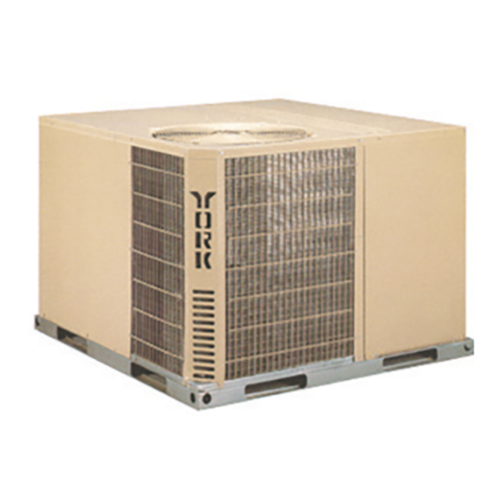
UPG Model BUZ units are factory assembled heat pumps
designed for outdoor installation on a roof top or a slab. Field-
installed electric heater accessories are available to provide
supplemental electric heat combined with electric cooling and
heating.
The units are completely assembled on rigid, removable base
rails. All piping, refrigerant charge, and electrical wiring is
factory installed and tested. The units require only electric
power and duct connections at the point of installation.
The electric heaters have nickel-chrome resistance wire
elements and utilize single point power connection.
Safety Considerations
This is a safety alert symbol
labels or in manuals, be alert to the potential for personal injury.
Understand and pay particular attention the signal words
DANGER, WARNING or CAUTION.
TABLE OF CONTENTS
LIST OF TABLES
LIST OF FIGURES
. When you see this symbol on
Compressors. . . . . . . . . . . . . . . . . . . . . . . . . . . . . . . . . . . 12
Phasing . . . . . . . . . . . . . . . . . . . . . . . . . . . . . . . . . . . . . . . 12
Airflow Performance . . . . . . . . . . . . . . . . . . . . . . . . . . . . . . . 13
Operation . . . . . . . . . . . . . . . . . . . . . . . . . . . . . . . . . . . . . . . 15
Anti-short Cycle Timer. . . . . . . . . . . . . . . . . . . . . . . . . . . . 15
Cooling Sequence Of Operations . . . . . . . . . . . . . . . . . . . 15
Heating Sequence Of Operations . . . . . . . . . . . . . . . . . . . 16
Maintenance . . . . . . . . . . . . . . . . . . . . . . . . . . . . . . . . . . . . . 18
Normal Maintenance . . . . . . . . . . . . . . . . . . . . . . . . . . . . . 18
Troubleshooting . . . . . . . . . . . . . . . . . . . . . . . . . . . . . . . . . . 18
Typical Wiring Diagrams . . . . . . . . . . . . . . . . . . . . . . . . . . 19
9 Additional Static Resistance . . . . . . . . . . . . . . . . . . . . . . 14
10 Electric Heat Minimum Supply Air . . . . . . . . . . . . . . . . . 15
11 Indoor Blower Specifications . . . . . . . . . . . . . . . . . . . . . . 15
12 Electric Heat Multipliers . . . . . . . . . . . . . . . . . . . . . . . . . 15
13 Demand Defrost Selection . . . . . . . . . . . . . . . . . . . . . . . 16
14 Thermostat Signals (Single Phase Units) . . . . . . . . . . . . 17
15 Thermostat Signals (Three Phase Units) . . . . . . . . . . . . 17
6 Roof Curb . . . . . . . . . . . . . . . . . . . . . . . . . . . . . . . . . . . . . 7
7 Typical Field Control Wiring Diagram . . . . . . . . . . . . . . . 9
8 Typical Field Power Wiring Diagram . . . . . . . . . . . . . . . 10
9 Demand Defrost "Curve" Selection Jumper . . . . . . . . . . 16
10 R-410A Quick Reference Guide . . . . . . . . . . . . . . . . . . 22
DANGER indicates an imminently hazardous situation, which,
if not avoided, will result in death or serious injury.
WARNING indicates a potentially hazardous situation, which,
if not avoided, could result in death or serious injury.
CAUTION indicates a potentially hazardous situation, which, if
not avoided may result in minor or moderate injury. It is also
used to alert against unsafe practices and hazards involving
only property damage.
Improper installation may create a condition where the
operation of the product could cause personal injury or
property damage. Improper installation, adjustment,
alteration, service or maintenance can cause injury or
property damage. Refer to this manual for assistance or
for additional information, consult a qualified contractor,
installer or service agency.
SO 9001
Certified Quality
Management System
268723-BIM-C-0908
Advertisement
Table of Contents

Subscribe to Our Youtube Channel
Related Manuals for York BUZ024


Summary of Contents for York BUZ024
-
Page 1: Table Of Contents
R-410A BUZ024-060 SO 9001 Certified Quality 2-5 Ton Management System TABLE OF CONTENTS General ......... . 1 Compressors. - Page 2 Reference Additional information is available in the following reference forms: • Technical Guide - BUZ024-060, 279853 Before performing service or maintenance operations on • General Installation - BUZ024-060, 268723 unit, turn off main power switch to unit. Electrical shock •...
-
Page 3: Installation
268723-BIM-C-0908 Installation Refer to Table 6 for unit physical data and to Table 5 for electrical data. Limitations If components are to be added to a unit to meet local codes, they are to be installed at the dealer's and/or the customer's These units must be installed in accordance with the following expense. -
Page 4: Location
268723-BIM-C-0908 Location Rigging And Handling Use the following guidelines to select a suitable location for Exercise care when moving the unit. Do not remove any these units. packaging until the unit is near the place of installation. Rig the unit by attaching chain or cable slings to the lifting holes Unit is designed for outdoor installation only. -
Page 5: Unit Accessory Weights
268723-BIM-C-0908 Table 2: Unit Accessory Weights Weight (lbs.) Unit Accessory Model Shipping Operating Add Economizer Add Electric Heat 1. Weight given is for the maximum heater size available (25 kW). HIGH VOLTAGE CONN. 7/8" DIA. KNOCKOUT FRONT HIGH VOLTAGE CONN. COMPRESSOR SERVICE ACCESS COMPARTMENT 1-31/32"... -
Page 6: Dimensions Front And Bottom
268723-BIM-C-0908 FRONT LOW VOLTAGE CONN. 7/8" DIA. KNOCKOUT HIGH VOLTAGE CONN. 1-31/32" x 7/8" KNOCKOUT CONDENSATE DRAIN 3/4" NPTF 40-1/2 26-3/4 22-1/2 43-1/2 Figure 4: Dimensions Front and Bottom SIDE SUPPLY 14-1/2 AIR OPENING 28-3/8 CONDENSER COIL 14-1/2 BACK BOTTOM SUPPLY AIR OPENING 3-3/8 SIDE RETURN... -
Page 7: Ductwork
268723-BIM-C-0908 RECOMMENDED DUCT SIZE 17-1/2" x 16-3/4" 42-2/3 45-1/8 40-3/4 17-5/8 17-1/4 43-1/4 OPENING FOR 3-1/2 RETURN AIR DUCT OPENING FOR SUPPLY AIR DUCT RECOMMENDED DUCT SIZE 17-1/8" x 21-1/2" Figure 6: Roof Curb Ductwork NOTE: Be sure to note supply and return openings. Refer to Figures 4 and 5 for information concerning rear and These units are adaptable to downflow use as well as rear bottom supply and return air duct openings. -
Page 8: Condensate Drain
268723-BIM-C-0908 Condensate Drain A condensate trap is recommended to be installed in the condensate drain. The plumbing must conform to local codes. Wear safety glasses and gloves when handling Use a sealing compound on male pipe threads. Install the refrigerants. Failure to follow this warning can cause condensate drain line (3/4”... -
Page 9: Typical Field Control Wiring Diagram
268723-BIM-C-0908 UNIT CONTROL BOARD NOTE: HEAT ANTICIPATOR THERMOSTAT TERMINAL STRIP SHOULD BE SET AT 0.25 AMPS FOR ALL MODELS. ** = Minimum wire size of 18 AWG wire should be used for all field installed 24 volt wire. * = Only required on units with supplemental electric heat. -
Page 10: Electrical Data
268723-BIM-C-0908 Figure 8: Typical Field Power Wiring Diagram Table 5: Electrical Data OD Fan Supply Compressors Max Fuse Motors Blower Electric Heat Option Size (each) Volt Breaker Size (each) Motor (Tons) (Amps) (Amps) RLA LRA MCC Model Stages Amps None 21.3 2NH04500506 3.8 / 5... -
Page 11: Physical Data
1. Minimum Circuit Ampacity. 2. Maximum Over Current Protection per standard UL 1995. 3. Fuse or HACR circuit breaker size installed at factory or field installed. Table 6: Physical Data Models Component BUZ024 BUZ030 BUZ036 BUZ042 BUZ048 BUZ060 Nominal Tonnage... -
Page 12: Compressors
268723-BIM-C-0908 Table 6: Physical Data (Continued) Models Component BUZ024 BUZ030 BUZ036 BUZ042 BUZ048 BUZ060 Nominal Tonnage CONDENSER FAN DATA Fan diameter (Inch) Type Prop Prop Prop Prop Prop Prop Drive type Direct Direct Direct Direct Direct Direct No. speeds Number of motors... -
Page 13: Ton
268723-BIM-C-0908 Airflow Performance Table 7: Side Duct Application External Static Pressure (Inches Water Gauge) Size Blower Speed Setting (Tons) Low (1) Low/Medium (2) Medium (3) (2.0) Medium/High (4) 1019 1097 High (5) 1052 1120 Low (1) Low/Medium (2) 1003 Medium (3) 1091 1041 1033... -
Page 14: Additional Static Resistance
268723-BIM-C-0908 Table 9: Additional Static Resistance Size Wet Indoor Coil Economizer Filter/Frame Kit Electric Heat (Tons) 0.01 0.00 0.01 0.02 0.01 0.00 0.02 0.03 0.01 0.00 0.02 0.03 0.01 0.01 0.02 0.03 (2.0) 0.01 0.01 0.02 0.04 1000 0.02 0.01 0.02 0.04 1100... -
Page 15: Operation
268723-BIM-C-0908 Table 10: Electric Heat Minimum Supply Air Minimum Supply Air (CFM) Size Voltage Heater kW (Tons) 10.0 15.0 20.0 25.0 208/230-1-60 (2.0) 208/230-1-60 208/230-3-60 (2.5) 460-3-60 208/230-1-60 1070 1070 1070 1070 208/230-3-60 1070 1070 1070 1070 (3.0) 460-3-60 1070 1070 1070 1070... -
Page 16: Heating Sequence Of Operations
268723-BIM-C-0908 Heating Sequence Of Operations Table 13: Demand Defrost Selection When the fan switch on the thermostat is in the “ON” Unit Pin Position position, the 24 volts at “G” brings on the indoor blower B*UZ 036, 048, 060 motor at the heating flow. When the fan switch on the B*UZ 024, 030 thermostat is in the “AUTO”... -
Page 17: Thermostat Signals (Single Phase Units)
268723-BIM-C-0908 Table 14: Thermostat Signals (Single Phase Units) Signal State Board Function FAN INSTANT ON FAN INSTANT OFF FAN INSTANT ON COMPRESSOR AND OUTDOOR FAN INSTANT ON (AFTER ANTI-SHORT CYCLE DELAY) REVERSING VALVE ENERGIZED G & Y & O SYSTEM OPERATES IN COOLING COMPRESSOR AND OUTDOOR FAN INSTANT OFF FAN 60 SEC. -
Page 18: Maintenance
268723-BIM-C-0908 Table 15: Thermostat Signals (Three Phase Units) (Continued) Signal State Board Function FAN INSTANT ON HEATER BANK 1, 2 & 3 ELEC. HEAT INSTANT ON HEATER BANK 4, 5 & 6 ELEC. HEAT 10 SEC. DELAY ON G & W HEATER BANK 4, 5 &... -
Page 19: Typical Wiring Diagrams
268723-BIM-C-0908 Typical Wiring Diagrams Typical BUZ024-060 Heat Pump 208/230-1-60 volt Wiring Diagram Johnson Controls Unitary Products... - Page 20 268723-BIM-C-0908 Typical BUZ030-060 Heat Pump 230-3-60 volt Wiring Diagram Johnson Controls Unitary Products...
- Page 21 268723-BIM-C-0908 Typical BUZ030-060 Heat Pump 460-3-60 volt Wiring Diagram Johnson Controls Unitary Products...
-
Page 22: 410A Quick Reference Guide
268723-BIM-C-0908 R-410A QUICK REFERENCE GUIDE Refer to Installation Instructions for specific installation requirements. R-410A efrigerant operates at 50 - 70 percent higher pressures than R-22. Be sure that servicing equipment and replacement components are designed to operate with R-410A. R-410A efrigerant cylinders are rose colored. Recovery cylinder service pressure rating must be 400 psig, DOT 4BA400, or DOT BW400. - Page 23 268723-BIM-C-0908 Johnson Controls Unitary Products...
- Page 24 Subject to change without notice. Printed in U.S.A. 268723-BIM-C-0908 Copyright © 2008 by Johnson Controls, Inc. All rights reserved. Supersedes: 268723-BIM-B-0807 Johnson Controls Unitary Products 5005 York Drive Norman, OK 73069...
Need help?
Do you have a question about the BUZ024 and is the answer not in the manual?
Questions and answers