Table of Contents
Advertisement
Quick Links
Advertisement
Table of Contents

Related Manuals for Fonrich FR-DCMG-MMPY


Summary of Contents for Fonrich FR-DCMG-MMPY
- Page 1 User Manual Version 4.2 DC System Monitor: FR-DCMG-MMPY 丰郅(上海)新能源科技有限公司 Fonrich (Shanghai) New Energy Technology Co., Ltd. Add: 1st Floor, Building 5, No.999 Jiangyue Road, Minhang District,Shanghai Web: www.fonrich.com Tel: +86 21 61679671 Email: sales@fonrich.com...
-
Page 2: Table Of Contents
Table of Contents Product description ............................3 The main function ............................. 3 Documentation statement ........................3 Terminal definition ............................ 4 Controller connection diagram ......................5 Ground connection and communication shield ................6 Operation interface display ..........................7 Key operation ............................. 7 Initial interface display .......................... -
Page 3: Product Description
Current calibration: identify zero drift and improve the accuracy of current • identification. (Default off) Compatibility:Program compatible model FR-DCMG-MMPD products • Documentation statement This manual is applicable to the monitoring host whose model is FR-DCMG-MMPY. The software version is A0F2. See page 11 for software version viewing method... -
Page 4: Terminal Definition
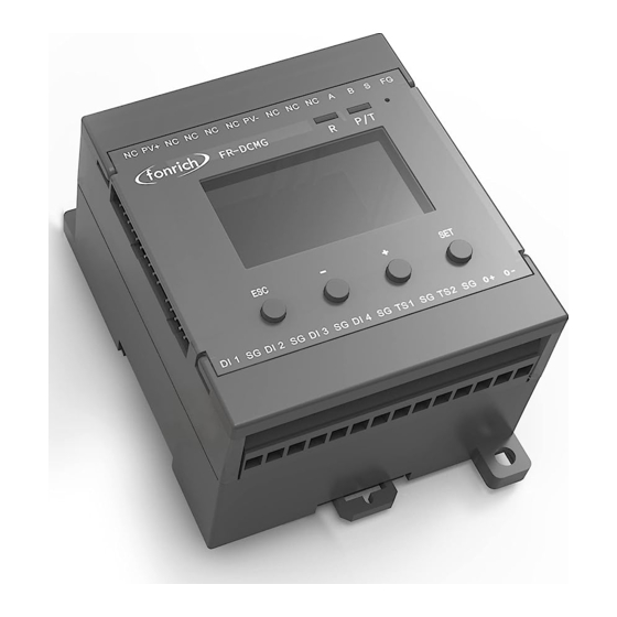
Terminal definition Symbol Meaning PV DC bus power supply terminal PV+ . PV- Not connecion Not connecion RS485 Communication terminal Fixed Ground terminal Externally connected temperature sensor terminals TS1.TS2 Temperature sensor and digital input ground terminal 4 digital input terminals DI1.DI2.DI3.DI4 Can connect modules with FUC interface Modules with an FMB interface can be connected, such as the FR-DCMG-AS4A... -
Page 5: Controller Connection Diagram
Controller connection diagram... -
Page 6: Ground Connection And Communication Shield
Ground connection and communication shield The FG terminal of the FR-DCMG must be grounded, otherwise communication will interfere and the reliability of the device will decrease. The grounding wire should be grounded nearby. The grounding wire should be no more than 15cm from the “FG” terminal to the bottom of the combiner box. -
Page 7: Operation Interface Display
Operation interface display Key operation FR-DCMG-MMPY has four keys “ESC”, “-”, “+”, and “SET”. "ESC" key is used to return to the default interface and cancel parameter setting; “SET”key is used to enter the parameter setting mode, select the parameter to be set and complete the setting of the parameter;... - Page 8 The order of the current channels can also be set in reverse order. The lightning icon in the upper left corner indicates that the FR-DCMG-MMPY horn- connected Hall sensor with arc monitoring function; "24" indicates the current online arc and current channel number;...
-
Page 9: Channel Current And Power Generation Display Interface
Channel current and power generation display interface In the histogram mode, press the "+" or "-" key to enter the channel current and power generation display interface. The current value and cumulative power generation of each channel are displayed on the screen. When the "+" key is pressed first, the digital value of the current is displayed first, and when the "-"... -
Page 10: Parameter Setting Interface
Parameter setting interface In the histogram interface, press the "SET" key to enter the Modbus parameter setting interface. The Modbus parameter setting is as follows: • ADDR: The communication address of the Modbus slave node, the range is 1 ~ 247 (default is 247). -
Page 11: Alarm Status Display Interface
HV:Keep • SV:Software version number • ST:Keep • Alarm status display interface Alarm messages can be cleared remotely and manually. Manual clearing requires long-pressing the host's "ESC" key for 2 seconds, remote clearing requires writing "1" to register 0x0079 to clear. If an arc alarm occurs, it must be cleared manually or remotely. Restarting the host will still display the alarm message. -
Page 12: Items That Can Generate Alarms Can Be Set
system jumps out of the interface as shown below, indicating that the alarm status has been cleared; remote processing needs to write "1" to 0x0079 to clear, and the interface shown below will be displayed after clearing successfully. Items that can generate alarms can be set Voltage is too high Voltage is too low Temperature is too high... -
Page 13: Alarm Message
Current reverse, no current, under current, over current, low current, high current, etc. Only when the average value of the channel current is greater than the set alarm threshold of the current channel, the alarm function of the above current-related items is activated; otherwise, the alarm status is forcibly cleared to 0. -
Page 14: Modbus Protocol Definition
MODBUS Protocol definition Communication format configuration Modbus communication mode: RTU mode • Address of the slave device: range form 1 to 247 (default 247) • Baud rate (bps): 2400, 4800, 9600 (default), 19200, 38400 • Byte check mode: odd check, even check, no check (default) •... -
Page 15: Register Description
The contents represented by the register in bits are: switch value, alarm information, etc. Register read and write in word units Function codes 03、04 are used to read multiple word-type registers • Function code 06 is used to write single word-type registers •... - Page 16 alarm status position is 1, and the alarm is cleared. 0x0237 Total reverse current This bit is set when the total reverse current exceeds the alarm alarm status threshold. Cleared below the alarm release threshold 0x0238 Total current too low This bit is set when the total current exceeds the alarm alarm state threshold.
- Page 17 0x0264 Channel 5 arc alarm status When the arc intensity of the channel is greater than the alarm threshold, this bit is set to 1; after clearing the alarm, it is set to 0x0265 Channel 6 arc alarm status When the arc intensity of the channel is greater than the alarm threshold, this bit is set to 1;...
- Page 18 0x0270 Channel 17 arc alarm When the arc intensity of the channel is greater than the alarm status threshold, this bit is set to 1; after clearing the alarm, it is set to 0x0271 Channel 18 arc alarm When the arc intensity of the channel is greater than the alarm status threshold, this bit is set to 1;...
- Page 19 0x0284 Channel 5 current reverse This bit is set when the channel current is reversed and greater alarm status than the alarm threshold, otherwise cleared. 0x0285 Channel 6 current reverse This bit is set when the channel current is reversed and greater alarm status than the alarm threshold, otherwise cleared.
- Page 20 0x0295 Channel 22 current This bit is set when the channel current is reversed and greater reverse alarm status than the alarm threshold, otherwise cleared. 0x0296 Channel 23 current This bit is set when the channel current is reversed and greater reverse alarm status than the alarm threshold, otherwise cleared.
- Page 21 0x02AD Channel 14 no current This bit is set to 1 when there is no current in this channel, alarm status otherwise cleared. 0x02AE Channel 15 no current This bit is set to 1 when there is no current in this channel, alarm status otherwise cleared.
- Page 22 0x02C5 Channel 6 undercurrent This bit is set to 1 when the channel is undercurrent, otherwise alarm status cleared. 0x02C6 Channel 7 undercurrent This bit is set to 1 when the channel is undercurrent, otherwise alarm status cleared. 0x02C7 Channel 8 undercurrent This bit is set to 1 when the channel is undercurrent, otherwise alarm status cleared.
- Page 23 alarm status cleared. 0x02D7 Channel 24 undercurrent This bit is set to 1 when the channel is undercurrent, otherwise alarm status cleared............. 0x02DF Channel 32 undercurrent This bit is set to 1 when the channel is undercurrent, otherwise alarm status cleared.
- Page 24 0x02EE Channel 15 overcurrent This bit is set to 1 when the channel is overcurrent, otherwise alarm status cleared. 0x02EF Channel 16 overcurrent This bit is set to 1 when the channel is overcurrent, otherwise alarm status cleared. 0x02F0 Channel 17 overcurrent This bit is set to 1 when the channel is overcurrent, otherwise alarm status cleared.
- Page 25 0x0306 Channel 7 current low This bit is set to 1 when the channel current is too low, alarm state otherwise cleared. 0x0307 Channel 8 current low This bit is set to 1 when the channel current is too low, alarm state otherwise cleared.
- Page 26 0x0317 Channel 24 current low This bit is set to 1 when the channel current is too low, alarm state otherwise cleared.............. 0x031F Channel 32 current low This bit is set to 1 when the channel current is too low, alarm state otherwise cleared.
- Page 27 0x032F Channel 16 current too This bit is set to 1 when the channel current is too high, high alarm state otherwise cleared. 0x0330 Channel 17 current too This bit is set to 1 when the channel current is too high, high alarm state otherwise cleared.
-
Page 28: Register Description In Word Unit (Function Code 03 04 06)
Register description in word unit (function code 03 04 06) Modbus address Function description Data Type instruction Decimal Address 0x0100 ~ 0x0158, a total of 89 consecutive addresses Address 0x0100 ~ 0x0123, a total of 36 consecutive addresses (data in this address supports data freeze) 0x0100 Broadcast time-year, Unsigned... - Page 29 bit14 channel current value is high 0: No alarm, 1: Alarm, default 0 0x014B Channel 1 ~ 16 reverse Unsigned Default 0 current alarm short 0: No alarm, 1: Alarm 0x014C Channel 17 ~ 32 reverse Unsigned Default 0 current alarm short 0: No alarm, 1: Alarm 0x014D...
- Page 30 channel1 …… …… ………… …… ………… …… 0x0262 The higher 16bit of the Unsigned Unit Wh, default 0 generated energy of short Channel 32 0x0263 The lower 16bit of the Unsigned Unit Wh, default 0 generated energy of short Channel 32 System information configuration (0x0B00-0x0B24) 0x0B00 2816...
- Page 31 0x0B0D 2839 0x0B0E 2830 Channel arc intensity super Short The default is 70.Need to set according to high alarm threshold the site conditions or customer requirements, you can call the company's technical staff 0x0B0F 2831 Retain 0x0B10 2832 Retain 0x0B11 2833 Automatic current Bool...
- Page 32 0 means positive order; 1 means reverse order bit3: Channel current direction setting 0 means the direction is positive, 1 means the current is reversed. 0x0000 by default; 0x0B17 2839 Retain 0x0B20 2848 Alarm function Unsigned Bit0 Bus arc, management 1 short bit1 Channel arc, bit2 Low pressure,...
- Page 33 values. 0xFE01 65025 Modbus Baud rate Unsigned 1:2400,2:4800,3:9600,4: short 19200,5:38400 Default is 3 0xFE02 65026 Modbus Parity Unsigned 0: NONE, 1: ODD, 2: EVEN short Default is 0...
-
Page 34: Appendix
Appendix Troubleshooting for screen flicker(Please refer to page 3 of the manual to deal with the problem of excessive interference from shielded wires)... -
Page 35: Document Revision Record
Document revision record Revision Time Description 1. Add the alarm recording function of trip failure; 2. Receive background authorization; 3. Support to read the log through 2016-4-16 Modus. 1. Realize automatic allocation of address; 2. Add data freezing 2016-5-03 function; 3. Add broadcasting function. 1. - Page 36 ——FAQ (screen flicker troubleshooting method) ——Controller connection diagram Deletion-Broadcast, battery board and other registers For A028 and above products 2020-07-06 ——HS4Q large range registers 0x0400, 0x0500 2020-07-20 Register update suitable for FR-DCMG-MMPY products...
-
Page 37: Contact Us
If you have any questions about this product, please contact us. Please remember the following contact information: Fonrich (Shanghai) New Energy Technology Co., Ltd. Add: 1st Floor, Building 5, No.999 Jiangyue Road, Minhang District,Shanghai Zip code: 201114 Tel :+86 21 61679672 Fax:+86 21 60717306 Email:sales@fonrich.com...
Need help?
Do you have a question about the FR-DCMG-MMPY and is the answer not in the manual?
Questions and answers