Table of Contents
Advertisement
Advertisement
Table of Contents

Related Manuals for Fonrich FR-DCMG-MMPU


Summary of Contents for Fonrich FR-DCMG-MMPU
- Page 1 User Manual Version 4.3 DC System Monitor: FR-DCMG-MMPU 丰郅(上海)新能源科技有限公司 Fonrich (Shanghai) New Energy Technology Co., Ltd. Add: 1st Floor, Building 5, No.999 Jiangyue Road, Minhang District,Shanghai Web: www.fonrich.com Tel: +86 21 61679671 Email: sales@fonrich.com...
-
Page 2: Table Of Contents
Table of Contents Product description ............................3 Main Features ............................. 3 Document Note ............................3 Terminals Definition ..........................4 Terminals Connection Comments ......................5 RS485 Cable Connection, Shielding, and Grounding ..............6 Operation interface display ..........................7 Button Key Operation ..........................7 Indication Leds ............................ -
Page 3: Product Description
When the alarm occurs, the interface will pop up an alarm message. Current calibration: identify zero drift and improve the accuracy of current • identification. (Default off) Document Note: This manual is for FR-DCMG-MMPU with firmware version A028 or above.See page 10 for firmware version viewing method... -
Page 4: Terminals Definition
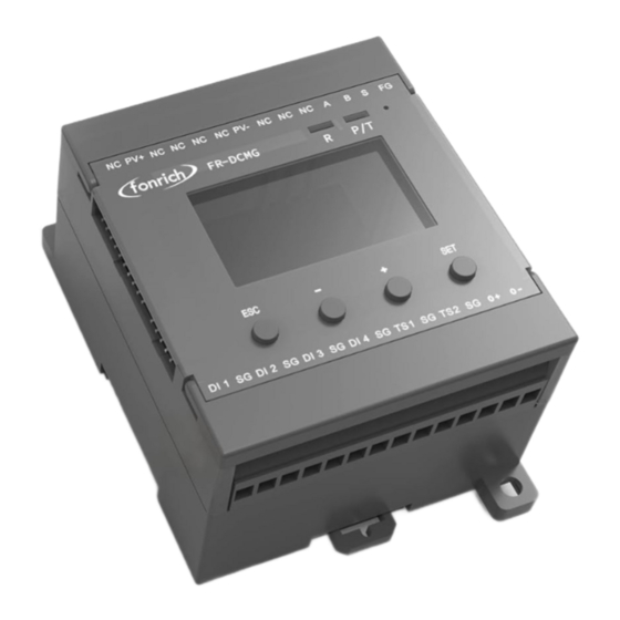
Terminals Definition Symbol Meaning PV DC bus power supply terminal PV+ . PV- Not connecion Not connecion RS485 Communication terminal Fixed Ground terminal Externally connected temperature sensor terminals TS1.TS2 Temperature sensor and digital input ground terminal 4 digital input terminals DI1.DI2.DI3.DI4 Can connect modules with FUC interface Modules with an FMB interface can be connected, such as the FR-DCMG-AS4A... -
Page 5: Terminals Connection Comments
Terminals Connection Comments:... -
Page 6: Rs485 Cable Connection, Shielding, And Grounding
RS485 Cable Connection, Shielding, and Grounding The FG terminal of the FR-DCMG must be grounded, otherwise communication will interfere and the reliability of the device will decrease. The grounding wire should be grounded nearby. The grounding wire should be no more than 15cm from the “FG” terminal to the bottom of the combiner box. -
Page 7: Operation Interface Display
Operation interface display Button Key Operation FR-DCMG-MMPU has four keys “ESC”, “-”, “+”, and “SET”. "ESC" key is used to return to the default interface and cancel parameter setting; “SET”key is used to enter the parameter setting mode, select the parameter to be set and complete the setting of the parameter;... - Page 8 The order of the current channels can also be set in reverse order. The lightning icon in the upper left corner indicates that the FR-DCMG-MMPU horn- connected Hall sensor with arc monitoring function; "24" indicates the current online arc and current channel number;...
-
Page 9: Channel Current And Power Generation Display Interface
Channel current and power generation display interface In the histogram mode, press the "+" or "-" key to enter the channel current and power generation display interface. The current value and cumulative power generation of each channel are displayed on the screen. When the "+" key is pressed first, the digital value of the current is displayed first, and when the "-"... -
Page 10: Parameter Setting Interface
Parameter setting interface In the histogram interface, press the "SET" key to enter the Modbus parameter setting interface. The Modbus parameter setting is as follows: • ADDR: The communication address of the Modbus slave node, the range is 1 ~ 247 (default is 247). -
Page 11: Alarm Status Display Interface
HV:Keep • SV:Software version number • ST:Keep • Alarm status display interface Alarm messages can be cleared remotely and manually. Manual clearing requires long-pressing the host's "ESC" key for 2 seconds, remote clearing requires writing "1" to register 0x0079 to clear. If an arc alarm occurs, it must be cleared manually or remotely. Restarting the host will still display the alarm message. -
Page 12: Items That Can Generate Alarms Can Be Set
system jumps out of the interface as shown below, indicating that the alarm status has been cleared; remote processing needs to write "1" to 0x0079 to clear, and the interface shown below will be displayed after clearing successfully. Items that can generate alarms can be set Voltage is too high Voltage is too low Temperature is too high... -
Page 13: Alarm Message
Current reverse, no current, under current, over current, low current, high current, etc. Only when the average value of the channel current is greater than the set alarm threshold of the current channel, the alarm function of the above current-related items is activated; otherwise, the alarm status is forcibly cleared to 0. -
Page 14: Modbus Protocol Definition
MODBUS Protocol definition Communication format configuration Modbus communication mode: RTU mode • Address of the slave device: range form 1 to 247 (default 247) • Baud rate (bps): 2400, 4800, 9600 (default), 19200, 38400 • Byte check mode: odd check, even check, no check (default) •... -
Page 15: Register Description
The contents represented by the register in bits are: switch value, alarm information, etc. Register read and write in word units Function codes 03、04 are used to read multiple word-type registers • Function code 06 is used to write single word-type registers •... - Page 16 alarm status position is 1, and the alarm is cleared. 0x0237 Total reverse current This bit is set when the total reverse current exceeds the alarm alarm status threshold. Cleared below the alarm release threshold 0x0238 Total current too low This bit is set when the total current exceeds the alarm alarm state threshold.
- Page 17 0x0264 Channel 5 arc alarm status When the arc intensity of the channel is greater than the alarm threshold, this bit is set to 1; after clearing the alarm, it is set to 0x0265 Channel 6 arc alarm status When the arc intensity of the channel is greater than the alarm threshold, this bit is set to 1;...
- Page 18 0x0270 Channel 17 arc alarm When the arc intensity of the channel is greater than the alarm status threshold, this bit is set to 1; after clearing the alarm, it is set to 0x0271 Channel 18 arc alarm When the arc intensity of the channel is greater than the alarm status threshold, this bit is set to 1;...
- Page 19 alarm status than the alarm threshold, otherwise cleared. 0x0286 Channel 7 current reverse This bit is set when the channel current is reversed and greater alarm status than the alarm threshold, otherwise cleared. 0x0287 Channel 8 current reverse This bit is set when the channel current is reversed and greater alarm status than the alarm threshold, otherwise cleared.
- Page 20 reverse alarm status than the alarm threshold, otherwise cleared. 0x0297 Channel 24 current This bit is set when the channel current is reversed and greater reverse alarm status than the alarm threshold, otherwise cleared..........0x02A0 Channel 1 no current This bit is set to 1 when there is no current in this channel, alarm status otherwise cleared.
- Page 21 0x02AF Channel 16 no current This bit is set to 1 when there is no current in this channel, alarm status otherwise cleared. 0x02B0 Channel 17 no current This bit is set to 1 when there is no current in this channel, alarm status otherwise cleared.
- Page 22 0x02C8 Channel 9 undercurrent This bit is set to 1 when the channel is undercurrent, otherwise alarm status cleared. 0x02C9 Channel 10 undercurrent This bit is set to 1 when the channel is undercurrent, otherwise alarm status cleared. 0x02CC Channel 11 undercurrent This bit is set to 1 when the channel is undercurrent, otherwise alarm status cleared.
- Page 23 0x02E1 Channel 2 overcurrent This bit is set to 1 when the channel is overcurrent, otherwise alarm status cleared. 0x02E2 Channel 3 overcurrent This bit is set to 1 when the channel is overcurrent, otherwise alarm status cleared. 0x02E3 Channel 4 overcurrent This bit is set to 1 when the channel is overcurrent, otherwise alarm status cleared.
- Page 24 0x02F2 Channel 19 overcurrent This bit is set to 1 when the channel is overcurrent, otherwise alarm status cleared. 0x02F3 Channel 20 overcurrent This bit is set to 1 when the channel is overcurrent, otherwise alarm status cleared. 0x02F4 Channel 21 overcurrent This bit is set to 1 when the channel is overcurrent, otherwise alarm status cleared.
- Page 25 0x030B Channel 12 current low This bit is set to 1 when the channel current is too low, alarm state otherwise cleared. 0x030C Channel 13 current low This bit is set to 1 when the channel current is too low, alarm state otherwise cleared.
- Page 26 0x0324 Channel 5 current too This bit is set to 1 when the channel current is too high, high alarm state otherwise cleared. 0x0325 Channel 6 current too This bit is set to 1 when the channel current is too high, high alarm state otherwise cleared.
- Page 27 0x0335 Channel 22 current too This bit is set to 1 when the channel current is too high, high alarm state otherwise cleared. 0x0336 Channel 23 current too This bit is set to 1 when the channel current is too high, high alarm state otherwise cleared.
-
Page 28: Register Description In Word Unit (Function Code 03 04 06)
Register description in word unit (function code 03 04 06) Modbus address Function description Data Type instruction Decimal Address 0x0100 ~ 0x0158, a total of 89 consecutive addresses Address 0x0100 ~ 0x0123, a total of 36 consecutive addresses (data in this address supports data freeze) 0x0100 Broadcast time-year, Unsigned... - Page 29 bit13 channel current value is low bit14 channel current value is high 0: No alarm, 1: Alarm, default 0 0x012E reserved 0x0130 Channel 1 ~ 16 arc alarm Unsigned Default 0 short 0: No alarm, 1: Alarm 0x0131 Channel 17 ~ 24 arc alarm Unsigned Default 0 short...
- Page 30 The address 0x0200 ~ 0x02FF, which has a total of 128 consecutive addresses. It is recommended to read in sections. Power information(0x0200-0x024b) 0x0200 Total power Unsigned Unit is 100W, default is 0 short 0x0201 Average power Unsigned Unit W, default 0 short 0x0202 Channel 1 ~...
- Page 31 0x0416 1046 Channel 23 current value short Unit 10mA, default 0 0x0417 1047 Channel 24 current value short Unit 10mA, default 0 0x0418 1048 Total reverse current short Unit 100mA, default 0 0x0419 1049 Total current short Unit 100mA, default 0 0x041A 1050 Average current...
- Page 32 alarm high threshold greater than -400 0x0B04 2820 Temperature sensor 2 short Unit 0.1 ° C, default 800, setting range is alarm high threshold greater than -400 0x0B05 2821 Total current low alarm Unsigned Unit 10mA, default 1600, (take 16 threshold Short channels to calculate)
- Page 33 0 means disabled, 1 means enabled Default 0xFFFF 0x0B14 2836 Channel 17~24 current Unsigned bit0:Represents the switch setting for channel switch setting short channel 7 bit7:Represents the switch setting for channel 24 0 means disabled, 1 means enabled Default 0xFFFF 0x0B15 2837 External power...
- Page 34 bit11 Channel current value is undercurrent, bit12 Channel current value is overcurrent, bit13 The channel current value is low, bit14 The channel current value is high, 1: enable (open) alarm, 0: disable(close) alarm Default:0x0003 0x0B21 2849 Alarm function Unsigned Bit0 DI1 management 2 short bit1 DI2...
- Page 35 short Set other values to restore the default values. 0xFE01 65025 Modbus Baud rate Unsigned 1:2400,2:4800,3:9600,4: short 19200,5:38400 Default is 3 0xFE02 65026 Modbus Parity Unsigned 0: NONE, 1: ODD, 2: EVEN short Default is 0 0xFE03 65027 reserved 0xFE04 65028 reserved 0xFE05...
- Page 36 System information (not open) 0xFE12 65042 CMB board software Unsigned System information (not open) version number short 0xFE13 65043 CMB board hardware Unsigned System information (not open) version number short 0xFE14 65044 CMB board hardware serial Unsigned System information (not open) number short 0xFE15...
- Page 37 The system default Modbus Master baud rate is 9600bps. Only after monitoring the battery board information, it attempts to adjust the baud rate. 0xFE1F 65055 modbus status Unsigned not open short 0xFE20 65056 Screen test Unsigned Write 1 black screen, write 2 white screen, File system short write 3 to restore the default display,...
-
Page 38: Appendix
Appendix Document revision record Revision Time Description 1. Add the alarm recording function of trip failure; 2. Receive background authorization; 3. Support to read the log through 2016-4-16 Modus. 1. Realize automatic allocation of address; 2. Add data freezing 2016-5-03 function;... -
Page 39: Contact Us
If you have any questions about this product, please contact us. Please remember the following contact information: Fonrich (Shanghai) New Energy Technology Co., Ltd. Add: 1st Floor, Building 5, No.999 Jiangyue Road, Minhang District,Shanghai Zip code: 201114 Tel :+86 21 61679672 Fax:+86 21 60717306 Email:sales@fonrich.com...
Need help?
Do you have a question about the FR-DCMG-MMPU and is the answer not in the manual?
Questions and answers