Table of Contents
Advertisement
Quick Links
Advertisement
Table of Contents

Subscribe to Our Youtube Channel
Related Manuals for Cloud CDR-1


Summary of Contents for Cloud CDR-1
- Page 1 CDR-1 & CDR1F Remote Control Units Installation Guide...
-
Page 3: Table Of Contents
Contents Introduction ..............4 Model types ....................4 What’s in the box ..................5 Installation ..............5 CDR networks and terminations ............5 Cable length and DC power considerations ........8 Wiring ......................9 Connecting and mounting – CDR‑1 ..........10 Connecting and mounting – CDR1F ..........13 Configuration .............. -
Page 4: Introduction
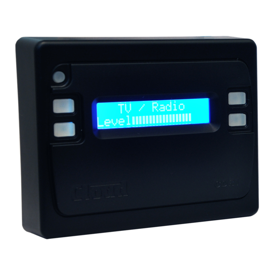
Introduction The CDR-1 & CDR1F are remote control units specifically designed for use with the DCM-1. They may be fitted to standard electrical back boxes in whatever location is convenient in each zone. Model types The CDR‑1 and CDR1F are electrically and operationally identical, but differ in their physical dimensions and mounting arrangements. -
Page 5: What's In The Box
What’s in the box As well as this manual, the shipping carton should contain the items listed below. Please contact your Cloud dealer immediately if any of them are missing. CDR-1 CDR1F CDR‑1 Remote Control panel CDR1F Remote Control panel Mounting plate 2x M3.5 panhead screws... - Page 6 Termination ON Termination ON DCM-1 CDR-1 PORTS PORT PORT PORT PORT All DCM-1terminations are OFF Termination ON Termination ON DCM-1 CDR-1 PORTS PORT PORT PORT PORT Termination ON Port A termination ON All other terminations are OFF Port A termination ON...
- Page 7 The correct termination setting is indicated for each device in the three wiring examples illustrated on page 6. See Step 5 of “Connecting and Mounting – CDR-1” on page page 11, or Step 3 of “Connecting and Mounting – CDR1F” on page 14 for details of how to set it.
-
Page 8: Cable Length And Dc Power Considerations
If a CDR is found to operate unreliably, it should be powered independently from a local PSU. The Cloud CPM‑PSU is suitable for this purpose, and should be connected to the EXT POWER socket at the rear of the CDR. In the case of the CDR‑1, this is a coaxial socket, mounted vertically on the PCB to the right (viewed from the rear). -
Page 9: Wiring
Wiring Feed the installed CAT‑5 cable(s) (or pre‑made patch cable(s)) into the back box on which the CDR is to be mounted. If not using pre‑made cables, crimp the RJ45 connector(s) as per the pinout diagram below: CAT‑5 CORE White + Orange Orange White + Green DC +ve... -
Page 10: Connecting And Mounting - Cdr-1
Connecting and mounting – CDR‑1 The CDR‑1 is designed for use with single‑gang UK, US or Australian electrical back boxes, using the mounting plate provided. It is also possible to mount it without a back box directly onto a wall. The mounting plate has several sets of fixing holes to accommodate the different styles of box. - Page 11 Check that jumper J1 is in the OFF position. J2 should be set according to the CDR-1’s position in the CAT-5 “chain”. If it is the final (or only) panel in the chain (i.e., nothing is plugged into the POWER OUT connector), set J2 to END; in all other cases set it to MID.
- Page 12 Push the bottom of the CDR‑1 towards the wall so that the two slots in the bottom of the housing line up with the tapped holes in the bottom of the plate. Mounting Plate CDR-1 Screw the CDR‑1 to the mounting plate using the two countersunk M3 screws removed in step 1.
-
Page 13: Connecting And Mounting - Cdr1F
Connecting and mounting – CDR1F The CDR1F is intended for use with dual‑gang UK size steel or PVC dry‑lining back boxes with an internal depth of 47 mm. As the internal electronic assembly is fully screened, It can also be mounted without a back box directly into a suitable wall cavity. Refer to page 14 for CDR1F dimensions In order for the display to be readily legible, only “landscape”... - Page 14 Check that jumper J1 is in the OFF position. J2 should be set according to the CDR1F’s position in the CAT-5 “chain”. If it is the final (or only) panel in the chain (i.e., nothing is plugged into the POWER OUT connector), set J2 to END; in all other cases set it to MID.
-
Page 15: Configuration
Configuration Each CDR must be assigned to a zone; this will normally be the zone in which it is physically located. As shipped from the factory, a CDR has no zone assigned, and when powered for the first time it will first display the backlight/contrast adjust screen, and then prompt for a zone assignment before continuing, as shown below: Use the + and –... -
Page 16: User Mode
• Reapply the power • Refit the remote control to its mounting plate with the two M3 screws (CDR-1) or to its back box/mounting hole with the front panel fixing screws (CDR1F). User mode The CDR’s normal operating state is User Mode, which permits selection of music source, level adjustment, and Group enabling/disabling (if available). -
Page 17: Default Settings
Default settings J1= OFF J2 = END KEY = “<<>>” Should you have any questions concerning the installation and connection of the CDR‑1/CDR1F please contact our Technical Support staff (details on rear cover). CDR‑1 & CDR1F Installation Guide v1.0... -
Page 18: Notes
Notes CDR‑1 & CDR1F Installation Guide v1.0... - Page 19 CDR‑1 & CDR1F Installation Guide v1.0...
- Page 20 Cloud Electronics Limited 140 Staniforth Road, Sheffield. S9 3HF. England Tel: +44 (0)114 244 7051 Fax: +44 (0)114 242 5462 email: info@cloud.co.uk web: www.cloud.co.uk...
Need help?
Do you have a question about the CDR-1 and is the answer not in the manual?
Questions and answers