Table of Contents
Advertisement
Quick Links
Advertisement
Table of Contents

Related Manuals for Norsat ATOMSKU Series


Summary of Contents for Norsat ATOMSKU Series
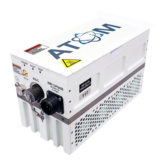
- Page 1 USER MANUAL ATOM Ku 80W BUC & SSPA...
- Page 2 Norsat does not assume any liability arising out of the application or use of any product or circuit described herein. Norsat does not convey any license under its patent rights or the rights of others.
-
Page 3: Table Of Contents
2.3 J3 – DC/AC Power ......................11 2.4 J2 – Monitor and Control Interface ................13 2.5 J4 – RF Output ......................27 2.6 Ground Connection .....................27 2.7 Indicators / LEDs ......................27 3.1 ATOM Installation ......................28 © Norsat International Inc. (“Norsat”) All Rights Reserved 2022-07-04 908236 Rev C... - Page 4 3.2 Fans & Baseplate Cooling ...................29 3.3 Accessories .........................29 3.4 General Specifications ....................29 3.5 Standard Warranty ......................30 © Norsat International Inc. (“Norsat”) All Rights Reserved 2022-07-04 908236 Rev C...
- Page 5 Figure A-3-1: 80W SSPA with AC Input & SMA Output……………………………………….31 Figure A-3-2: 80W BUC/SSPA with DC Input WR62/75 Output, Fan Cooled……………… 32 Figure A-3-3: 80W BUC/SSPA with DC Input WR62/75 Output, Baseplate Cooled………. 33 © Norsat International Inc. (“Norsat”) All Rights Reserved 2022-07-04 908236 Rev C...
- Page 6 Table 2-10: Getstatus Parameters and Data Types ..............23 Table 2-11: Getmute Parameters and Data Types ..............24 Table 2-12: Indicators / LEDs ....................28 Table 3-1: General 80W ATOM Specifications ................29 Table B-3-1: Acronyms and Abbreviations ................34 © Norsat International Inc. (“Norsat”) All Rights Reserved 2022-07-04 908236 Rev C...
-
Page 7: Overview
M&C Connector – a ten-pin connector is used to interface with a host computer. See Section 2.4 J2 – Monitor and Control Interface for detailed description of the pinouts. © Norsat International Inc. (“Norsat”) All Rights Reserved 2022-07-04 908236 Rev C... -
Page 8: Safety
Apply voltage to the AC/DC input connector only as specified in the original configuration of this unit. Application of a voltage outside the specified range may cause the unit to become damaged or non-functional. © Norsat International Inc. (“Norsat”) All Rights Reserved 2022-07-04 908236 Rev C... -
Page 9: Introduction
J3 – Four-pin circular power connector for DC unit or six-pin circular power connector for AC unit • J6 – Ground terminal Figure 2-1: Input Connections for ATOM 80W DC Unit © Norsat International Inc. (“Norsat”) All Rights Reserved 2022-07-04 908236 Rev C... -
Page 10: Figure 2-2: Input Connections For Atom 80W Ac Unit
J4 – WR75 or WR62 waveguide RF output • Optional Waveguide to Coax adaptor Figure 2-3: Standard Waveguide Output for Figure 2-4: Optional Waveguide to Coax ATOM 80W units adaptor © Norsat International Inc. (“Norsat”) All Rights Reserved 2022-07-04 908236 Rev C... -
Page 11: J1 & J6- Inputs And Grounding
Please contact the connector manufacturer for more information and/or refer to the Amphenol® catalog 12-070. Ensure the supply cable is capable of supplying at least 540W of power (for 80W ATOM). © Norsat International Inc. (“Norsat”) All Rights Reserved 2022-04-04 908236 Rev C... -
Page 12: Figure 2-5: Dc Unit J3 Connector Pinout
The mating Amphenol connector DL3106A18012S must be used to maintain the First-Make Last-Break feature. © Norsat International Inc. (“Norsat”) All Rights Reserved 2022-04-04 908236 Rev C... -
Page 13: J2 - Monitor And Control Interface
The standard M&C configuration includes RS-485 addressing capability. The 80W ATOM can be ordered with web interface or RS-232 serial interface options. Table 2-3 summarizes the M&C interface protocols available with each option. © Norsat International Inc. (“Norsat”) All Rights Reserved 2022-04-04 908236 Rev C... -
Page 14: Figure 2-7: J2 M&C Connector Pin Arrangement
Table 2-4 summarizes the various pinout options for the 80W ATOM. Note that the pin function varies according to the M&C interface option that the ATOM was ordered with. The M&C interface option cannot be changed by the user. © Norsat International Inc. (“Norsat”) All Rights Reserved 2022-04-04 908236 Rev C... -
Page 15: Table 2-4: J2 Pinouts For Atom Configurations
Host computer Rx- signal (signal RS-485 Rx- RS-485 Rx- out of unit) RS-485 ADD2 RS-485 Address 2 Ethernet host computer Rx- signal Eth Rx- (signal out of unit) © Norsat International Inc. (“Norsat”) All Rights Reserved 2022-04-04 908236 Rev C... -
Page 16: Table 2-5: Atom Mute Control Behavior
Tx+ and Tx- are the differential pair which carries a signal from the host computer to the unit. Rx+ and Rx- are the differential pair which carries a signal from the unit to the host computer. Connect these to the host computer RS-485 port accordingly. © Norsat International Inc. (“Norsat”) All Rights Reserved 2022-04-04 908236 Rev C... -
Page 17: Table 2-6: Rs-485 Address Assignment
Ethernet Interface Option: Pins E, F, H, & K These four pins form a standard 10/100Mbps Ethernet link. Table 2-7 and Figure 2-8 summarize how to construct an Ethernet M&C cable to access the web interface. © Norsat International Inc. (“Norsat”) All Rights Reserved 2022-04-04 908236 Rev C... -
Page 18: Figure 2-8: Rj-45 Plug Pinout
Note that it is possible to use an RS-232 interface to control a standard configuration equipped ATOM through an RS-485 to RS-232 adaptor. Contact Norsat for details about the available adaptor kits. Serial Port Interface (RS-485 & RS-232) Port Settings Communications to and from the serial interface is ASCII character based. -
Page 19: Table 2-8: Serial Port Interface Setup
For Addressed Commands, the <address> value must match the device’s RS-485 address specified via pins E, F, and K of the M&C connector. Addressed Commands sent to an address that does not match the © Norsat International Inc. (“Norsat”) All Rights Reserved 2022-04-04 908236 Rev C... - Page 20 If the device’s RS-485 address is between 0 and 6 (inclusive), the response format will be: <CR><LF><response><CRC><CR><LF> If the device’s RS-485 address is 7, the response format is: <CR><LF><response><CR><LF> © Norsat International Inc. (“Norsat”) All Rights Reserved 2022-04-04 908236 Rev C...
- Page 21 The following section provides detailed information about some of the basic commands that can be sent to the ATOM device. Commands are described in Non-addressed Mode for simplicity. getident This command obtains identification information from the ATOM device. Command Format: getident<CR> Response Format: © Norsat International Inc. (“Norsat”) All Rights Reserved 2022-04-04 908236 Rev C...
-
Page 22: Table 2-9: Getident Parameters And Data Types
This command obtains status information from the ATOM device. Command Format: getstatus<CR> Response Format: <CR><LF>ok fault <Fault Status> fwdpwr <RF Forward Power> revpwr <RF Reverse Power> temp <Device Temperature><CR><LF> © Norsat International Inc. (“Norsat”) All Rights Reserved 2022-04-04 908236 Rev C... -
Page 23: Table 2-10: Getstatus Parameters And Data Types
The device’s overall mute state is reported along with the faults. This bit will be set to 1 if the device is muted for any reason (software control, hardware control, or automatic muting due to one of the above three faults). © Norsat International Inc. (“Norsat”) All Rights Reserved 2022-04-04 908236 Rev C... -
Page 24: Table 2-11: Getmute Parameters And Data Types
Table 2-11: Getmute Parameters and Data Types Parameter Value Data Type Description value <Mute Status> 1 if the device is currently Muted, UINT16 or 0 if the device is currently Unmuted. © Norsat International Inc. (“Norsat”) All Rights Reserved 2022-04-04 908236 Rev C... - Page 25 The default IP Address for the ATOM unit is 192.168.77.30 and default the subnet mask is 255.255.255.0. Ensure the computer’s IP Address is on the same logical network and subnet as the ATOM unit (e.g. 192.168.77.XXX, where XXX is any number except “30”). © Norsat International Inc. (“Norsat”) All Rights Reserved 2022-04-04 908236 Rev C...
- Page 26 Using ATOMWeb Interface The ATOMWeb use and operation is identical to the ATOMControl interface. Refer to the ATOMControl Software Manual for instructions on how to use the web interface (Norsat document number INS001085). Changing the ATOM’s IP Address The factory default IP address of the BUC is 192.168.77.30 but it can be user configured through the Network and Port Configuration webpage.
-
Page 27: J4 - Rf Output
2.7 Indicators / LEDs There are three LEDs on the unit that indicate the unit status to the user. © Norsat International Inc. (“Norsat”) All Rights Reserved 2022-04-04 908236 Rev C... -
Page 28: Atom Installation
Depending on the configuration, an ATOM can weigh up to 7.3kg (16lbs). When choosing an installation location, ensure the mounting brackets are capable of supporting the unit weight. Norsat recommends that the unit is supported using at least eight of the mounting holes on two opposing sides (four holes per side). -
Page 29: Table 3-1: General 80W Atom Specifications
3.4 General Specifications : General 80W ATOM Specifications Table 3-1 summarizes general specifications applicable to most 80W ATOM units. Please refer to the specific ATOM datasheet available on the Norsat website for complete unit specifications. Table 3-1: General 80W ATOM Specifications Parameter... - Page 30 3.5 Standard Warranty Norsat International Incorporated warrants that its equipment shall be free from defects in material or workmanship for a period of one (1) year from the ship date, unless otherwise stated in the Offer Terms and Conditions. The warranty does not cover units that have: been damaged through improper use or physical damage (e.g.
-
Page 31: Figure A-3-1: 80W Sspa With Ac Input & Sma Output
INTAKE EXHAUST 6.431 INTAKE 3X #8-32 0.38 (BOTH SIDES) 6X 1/4-20 0.50 2X 0.365 2X 2.665 2X 4.965 Figure A-3-1: 80W SSPA with AC Input & SMA Output © Norsat International Inc. (“Norsat”) All Rights Reserved 2022-04-04 908236 Rev C... -
Page 32: Figure A-3-2: 80W Buc/Sspa With Dc Input Wr62/75 Output, Fan Cooled
INTAKE EXHAUST INTAKE 3X #8-32 0.38 (BOTH SIDES) 6X 1/4-20 0.50 2X 0.365 2X 2.665 2X 4.965 Figure A-3-2: 80W BUC/SSPA with DC Input WR62/75 Output, Fan Cooled © Norsat International Inc. (“Norsat”) All Rights Reserved 2022-04-04 908236 Rev C... -
Page 33: Figure A-3-3: 80W Buc/Sspa With Dc Input Wr62/75 Output, Baseplate Cooled
Figure A-3-3: 80W BUC/SSPA with DC Input WR62/75 Output, Baseplate Cooled © Norsat International Inc. (“Norsat”) All Rights Reserved 2022-04-04 908236 Rev C... -
Page 34: Table B-3-1: Acronyms And Abbreviations
Line Feed character (ASCII) M&C Monitor and Control Megahertz Millimeter Not Applicable Pulses per minute Radio Frequency Receive SSPA Solid State Power Amplifier Transmit Volt Volts Direct Current © Norsat International Inc. (“Norsat”) All Rights Reserved 2022-04-04 908236 Rev C... - Page 35 © Norsat International Inc. (“Norsat”) All Rights Reserved emergency services and homeland security 110 – 4020 Viking Way | Richmond | British Columbia | Canada 2022-04-04 908236 Rev C agencies, military organizations, health care providers and Fortune 1000 companies.