Table of Contents
Advertisement
Quick Links
Advertisement
Table of Contents

Related Manuals for Norsat ATOM Series


Summary of Contents for Norsat ATOM Series
- Page 1 ATOM 100-250W BUC & SSPA Revision 2.2 908236 ATOM 100-250W BUC & SSPA Operator’s Manual Document Number: 908236 Revision 2.2 Norsat International Inc. 110 – 4020 Viking Way Richmond, British Columbia Canada V6V 2L4 908236_r2.2 - Operator Manual ATOM KU 100-250W.doc...
-
Page 2: Operator's Manual
Norsat does not assume any liability arising out of the application or use of any product or circuit described herein. Norsat does not convey any license under its patent rights or the rights of others. -
Page 3: Revision History
ATOM 100-250W BUC & SSPA Revision 2.2 908236 EVISION ISTORY Reason For Change Reviewed Author Date yy/mm/dd 5521 Initial Release 13/11/14 5764 Add details on screw lengths for RF 14/04/29 Output and Ground Connection 5964 Update Address 14/09/05 6518 Update for Ethernet Interface JG/CW 15/12/15 Update M&C Protocol... -
Page 4: Table Of Contents
ATOM 100-250W BUC & SSPA Revision 2.2 908236 ABLE OF ONTENTS Operator’s Manual ..............................2 Technical Support ..............................2 Revision History ..............................3 Table of Contents ..............................4 List of Figures............................... 5 List of Tables ................................ 5 CHAPTER 1 INTRODUCTION ........................6 1.1 O .......................... -
Page 5: List Of Figures
ATOM 100-250W BUC & SSPA Revision 2.2 908236 IST OF IGURES Figure 2-1 Input Connections for ATOM 100W DC Unit ....................9 Figure 2-2 Input Connections for ATOM 100W AC Unit ....................10 Figure 2-3 Input Connections for ATOM 250W Unit ..................... 10 Figure 2-4 Standard Waveguide Output for ATOM 100W units ................... -
Page 6: Chapter 1 Introduction
ATOM 100-250W BUC & SSPA Revision 2.2 908236 Section 1.1 VERVIEW This operator’s manual applies to all ATOM SSPAs and BUCs with the following marketing numbers: ATOMSKUxxx (100-250W) ATOMBKUxxx (100-250W) This includes any ATOM that uses the 100-250W (P1dB) Ku Extended Band (13.75-14.5GHz) mechanics, such as a custom frequency band or power derated output unit. -
Page 7: Section 1.2 Features
ATOM 100-250W BUC & SSPA Revision 2.2 908236 Section 1.2 EATURES NPUTS AND UTPUTS Table 1-1: Input and Outputs 100-250W Female N-Type Connector (standard) Input Type Female SMA-Type Connector (optional) Waveguide WR75 (standard) Output Type Waveguide WR62 (optional/frequency dependent) LECTRICAL NTERFACE M&C Connector –... -
Page 8: Section 1.3 Safety
ATOM 100-250W BUC & SSPA Revision 2.2 908236 Section 1.3 AFETY W A R N I N G Leakage Current The ATOM may exhibit high leakage current during use. Ensure that the ground terminal is grounded according to local electrical codes prior to powering on the ATOM. W A R N I N G RF Radiation Hazard The ATOM emits high power RF energy which is harmful to... -
Page 9: Chapter 2 Interface Control
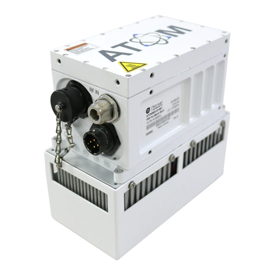
ATOM 100-250W BUC & SSPA Revision 2.2 908236 Section 2.1 NTRODUCTION The unit has three connectors on the input side of the housing and one waveguide port on the output side. The interface for these connectors is detailed in this document. On the input side, there are the following connectors: ... -
Page 10: Figure 2-2 Input Connections For Atom 100W Ac Unit
ATOM 100-250W BUC & SSPA Revision 2.2 908236 Figure 2-2 Input Connections for ATOM 100W AC Unit Figure 2-3 Input Connections for ATOM 250W Unit 908236_r2.2 - Operator Manual ATOM KU 100-250W.doc... -
Page 11: Figure 2-4 Standard Waveguide Output For Atom 100W Units
ATOM 100-250W BUC & SSPA Revision 2.2 908236 On the output side, there is one connector: J4 – WR75 or WR62 waveguide RF output Optional Waveguide to Coax adaptor Figure 2-4 Standard Waveguide Output for Figure 2-5 Optional Waveguide to Coax adaptor ATOM 100W units Figure 2-6 Standard Waveguide Output for ATOM 250W units 908236_r2.2 - Operator Manual ATOM KU... -
Page 12: J1, J5, & J6- Inputs And Grounding
ATOM 100-250W BUC & SSPA Revision 2.2 908236 Section 2.2 J1, J5, & J6– I NPUTS AND ROUNDING J1 – IF/RF I NPUT The IF/RF input connector is a 50 ohm coaxial connector (N or SMA Type). This connector is NOT DC- blocked, and appears as a 50 ohm load at DC. -
Page 13: J3 - Dc/Ac Power
ATOM 100-250W BUC & SSPA Revision 2.2 908236 Section 2.3 J3 – DC/AC P OWER The 100W ATOM power input requires either 20V to 56V DC power (DC unit) or 3-phase 208V AC power (AC unit). On the other hand, 250W ATOM power input requires 36V to 56V DC power. Each ATOM is supplied with a mating connector for the power interface. -
Page 14: Phase Ac Power Option
ATOM 100-250W BUC & SSPA Revision 2.2 908236 For the DC input units, the positive terminals are pins B/C and the negative terminals are pins A/D. Pins A and D are connected to case ground internally; pins B and C are connected together internally. It is recommended to apply the supply voltage evenly to both pairs of pins to evenly share the current among both sets of wires/pins. -
Page 15: J2 - Monitor And Ontrol Nterface
ATOM 100-250W BUC & SSPA Revision 2.2 908236 Section 2.4 J2 – M ONITOR AND ONTROL NTERFACE The M&C interface is used to control the unit with a host computer. All on-board sensors are accessed through this interface. Use of this connection is optional. Each ATOM is supplied with a mating connector for the M&C interface. -
Page 16: Table 2-4: J2 Pinouts For Atom Configurations
ATOM 100-250W BUC & SSPA Revision 2.2 908236 Table 2-4 summarizes the various pinout options for the 100-250W ATOM. Note that the pin function varies according to the M&C interface option that the ATOM was ordered with. The M&C interface option cannot be changed by the user. -
Page 17: Table 2-5: Atom Mute Control Behavior
ATOM 100-250W BUC & SSPA Revision 2.2 908236 Mute Control: Pin D This pin controls the hardware mute state of the ATOM. When muted, the power transistors are turned off, reducing power consumption and providing an RF output noise close to the thermal noise floor. The operation of this pin is fully configurable through the M&C Interface. -
Page 18: Figure 2-10: Rj-45 Plug Pinout
ATOM 100-250W BUC & SSPA Revision 2.2 908236 The RS-485 address pins each have a 10K-ohm pull up to 3.3V. If RS-485 addressing is not used, pins E, F, & K should be left floating (i.e. disconnected). Table 2-6 summarizes the unit address assignment configuration; 0 denotes a grounded pin and 1 indicates a floating pin. -
Page 19: Serial Port Interface (Rs-485 & Rs-232)
Note that it is possible to use an RS-232 interface to control a standard configuration equipped ATOM through an RS-485 to RS-232 adaptor. Contact Norsat for details about the available adaptor kits. (RS-485 & RS-232) ERIAL... - Page 20 ATOM 100-250W BUC & SSPA Revision 2.2 908236 The command format for Non-addressed Commands is as follows: <cmd><CR> Only a carriage return character is required for Non-addressed Command termination. In both cases, the <cmd> string is a command word (in ASCII text) followed by zero or more sets of parameter-value pairs.
- Page 21 ATOM 100-250W BUC & SSPA Revision 2.2 908236 Command Response The CLI operates on a command + response paradigm. Each time a command is entered, a response will be displayed. If the device’s RS-485 address is between 0 and 6 (inclusive), the response format will be: <CR><LF><response><CRC><CR><LF>...
- Page 22 ATOM 100-250W BUC & SSPA Revision 2.2 908236 Command Details The following section provides detailed information about some of the basic commands that can be sent to the ATOM device. Commands are described in Non-addressed Mode for simplicity. getident This command obtains identification information from the ATOM device. Command Format: getident<CR>...
- Page 23 ATOM 100-250W BUC & SSPA Revision 2.2 908236 Command Format: getstatus<CR> Response Format: <CR><LF>ok fault <Fault Status> fwdpwr <RF Forward Power> revpwr <RF Reverse Power> temp <Device Temperature><CR><LF> Value Data Type Notes <Fault Status> A hexadecimal value prefixed with “0x” that indicates UINT16 which of the four detectable faults have been detected.
- Page 24 ATOM 100-250W BUC & SSPA Revision 2.2 908236 The accurate forward power values range from Psat-15dB to Psat, or from 35dBm to 50dBm for an amplifier with a saturated power output of 100W. Values more than 15dB below Psat are not considered accurate.
-
Page 25: Ethernet Interface (Atomweb)
ATOM 100-250W BUC & SSPA Revision 2.2 908236 getmute<CR> <CR><LF>ok value 1<CR><LF> setmute This command controls the mute state for the ATOM device. Command Format: setmute value <Mute Command><CR> Response Format: <CR><LF>ok<CR><LF> Response Value: Value Data Type Notes <Mute Command> UINT16 1 if the software mute should be enabled, or 0 if the software mute should be disabled. - Page 26 Using ATOMWeb Interface The ATOMWeb use and operation is identical to the ATOMControl interface. Refer to the ATOMControl Software Manual for instructions on how to use the web interface (Norsat document number INS001085). Changing the ATOM’s IP Address The factory default IP address of the BUC is 192.168.77.30 but it can be user configured through the Network and Port Configuration webpage.
-
Page 27: J4 - Rf Output
ATOM 100-250W BUC & SSPA Revision 2.2 908236 3. Send the following command and the ATOM will respond with the IP Address ns getipdata<CR> ATOMWEB IP:192.168.0.145 MASK: 255.255.255.0<CR> 4. Follow the instructions in the preceding section to restore the IP Address to the desired setting. Ethernet Method (alternate method) 5. -
Page 28: Section 2.7 Indicators / Led S
ATOM 100-250W BUC & SSPA Revision 2.2 908236 Section 2.7 / LED NDICATORS There are three LEDs on the unit that indicate the unit status to the user. Table 2-9: Indicators / LEDs Color Name POWER Green On = Power on Off –... -
Page 29: Chapter 3 Misc. Info
1 inch must be maintained around the air intake and exhaust during use. The fans are a field replaceable assembly; contact Norsat for details on replacement kits. If the unit is deployed inside a radome, ensure there is adequate cooling to remove heat and prevent the unit from overheating. -
Page 30: Section 3.3 Accessories
Section 3.4 ENERAL PECIFICATIONS Table 3-1 summarizes general specifications applicable to most 100-250W ATOM units. Please refer to the specific ATOM datasheet available on the Norsat website for complete unit specifications. Table 3-1: General 100-250W ATOM Specifications Parameter Specifications RF Power Output (P1dB) -
Page 31: Section 3.5 Standard Warranty
TANDARD ARRANTY Norsat International Incorporated warrants that its equipment shall be free from defects in material or workmanship for a period of one (1) year from the ship date, unless otherwise stated in the Offer Terms and Conditions. The warranty does not cover units that have: been damaged through improper use or physical damage (e.g. -
Page 32: Mechanical Drawings
ATOM 100-250W BUC & SSPA Revision 2.2 908236 Mechanical Drawings 6X #8-32 0.25 (BOTH SIDES) 1.031 2X 1.031 2.131 2X 1.831 2.081 2.181 2.306 2X 2.631 3X 3.331 3X 3.331 INTAKE EXHAUST 6.431 INTAKE 3X #8-32 0.38 (BOTH SIDES) 6X 1/4-20 0.50 2X 0.365 2X 2.665 2X 4.965... -
Page 33: Figure A-3-2: 100W Buc/Sspa With Dc Input Wr62/75 Output, Fan Cooled
ATOM 100-250W BUC & SSPA Revision 2.2 908236 6X #8-32 0.25 (BOTH SIDES) 1.181 2X 1.031 2.131 2X 1.831 2.081 2.181 2.306 2X 2.631 3X 3.331 3X 3.331 INTAKE EXHAUST INTAKE 3X #8-32 0.38 (BOTH SIDES) 6X 1/4-20 0.50 2X 0.365 2X 2.665 2X 4.965 Figure A-3-2: 100W BUC/SSPA with DC Input WR62/75 Output, Fan Cooled... -
Page 34: Figure A-3-3: 100W Buc/Sspa With Dc Input Wr62/75 Output, Baseplate Cooled
ATOM 100-250W BUC & SSPA Revision 2.2 908236 6X #8-32 0.25 (BOTH SIDES) 1.031 1.031 2.131 1.831 2.081 2.181 2.306 2.631 3X 3.331 3.331 3.581 3.581 3X #8-32 0.38 (BOTH SIDES) 2X 0.750 5X 2.540 5X 3.685 5X 4.830 17X #8-32 0.25 (BOTH SIDES) Figure A-3-3: 100W BUC/SSPA with DC Input WR62/75 Output, Baseplate Cooled... -
Page 35: Figure A-3-4: 250W Buc/Sspa With Dc Input Wr62/75 Output, Baseplate Cooled
ATOM 100-250W BUC & SSPA Revision 2.2 908236 11.390 12.891 WR75 FLANGE 1/4-20 UNC 0.500 SHOWN 1/4-20 UNC 0.500 0.581 2X 1/4-20 UNC 0.500 2X 0.831 1.231 WAVEGUIDE 2X 2.031 OUTPUT FLANGE 2.481 2X 2.831 2X 3.231 INTAKE INTAKE 6.271 10-32 UNF 0.220 EXHAUST... -
Page 36: Acronyms And Abbreviations
ATOM 100-250W BUC & SSPA Revision 2.2 908236 Acronyms and Abbreviations The following is a list of acronyms and abbreviations referenced in this document. Table B-3-1: Acronyms and Abbreviations Acronym Definition Block Upconverter Amplifier Celsius <CR> Carriage Return character (ASCII) Decibel-milliwatts Direct Current Electrostatic Discharge...