
Subscribe to Our Youtube Channel
Related Manuals for Parker HB632


Summary of Contents for Parker HB632
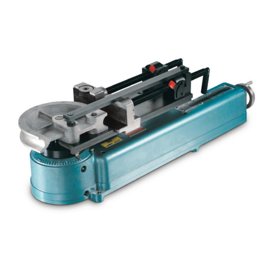
- Page 1 Bulletin 4391-B26 May 2001 FluidConnectors Parker Hydraulic Tube Bender, Model HB632 The Fitting Authority...
- Page 2 Offer of Sale The items described in this document are hereby offered for sale by Parker Hannifin Corporation, its subsidiaries or its authorized distributors. This offer and its acceptance are governed by the provisions stated in the “Offer of Sale”.
-
Page 3: Specifications
Minimum tube wall thickness (% of O.D.) 4% with mandrel, 7% without mandrel Min. tube size 3/8" The HB632 is capable of bending 1/2" O.D. and under fully annealed steel and Max. tube size 2" stainless steel tubing with no limit on tube wall thickness Min. - Page 4 The stop screws can be ad- justed for correct length and positioning of the mandrel in the tubing. Part Name Part No. 631141 – HB632 Mandrels, Mandrel Rods and Rod Stop Assembly Part No. Mandrel Rod Stop Assembly (for Bender Model HB632) ......
- Page 5 Max. Pipe Size (in.) (in.) Part No. (in.) Schedule 0.675 974325 2 1/4 0.840 974326 2 5/8 1.050 3 1/4 974327 1.315 974328 1 1/4 1.660 974329 1 1/2 1.900 974330 Parker Hannifin Corporation Tube Fittings Division FluidConnectors Columbus, OH...
- Page 6 3/8, 1/2, 3/4 0.675, 0.840, 1.050 974331 974332 1.315 1.315 974336 974338 1 1/4 1.660 974340 1 1/4 1.660 974341 1 1/2 1.900 974342 1 1/2 1.900 974343 Slide Block Clamp Block Parker Hannifin Corporation Tube Fittings Division FluidConnectors Columbus, OH...
- Page 7 The first bend is easy. Simply measure from the end of the tube to the desired length of the centerline* of the first bend. *For information on tube bending, centerline measurement, and back-bending compensation, see Parker Principles of Tube Line Fabrication, Manual 4306- Parker Hannifin Corporation Tube Fittings Division FluidConnectors...
- Page 8 Then bring into snug position against the tube, but not with so much pressure as to prevent the block from sliding freely. The clamp block and slide block should not be touching. Parker Hannifin Corporation Tube Fittings Division FluidConnectors Columbus, OH...
- Page 9 Your tubing is bent, without flattening or cracking. Releasing system pressure by opening the valve will relieve tension in the bender and the clamp arm will return to its original position. Parker Hannifin Corporation Tube Fittings Division FluidConnectors Columbus, OH...
- Page 10 (Although not an extrac- tor, this assembly is necessary to secure the mandrel and rod during the bending process.) The Parker bender table has pre-drilled holes for the bender and rod stop assembly attachment. These pre-drilled holes insure proper bender and rod stop assembly alignment.
- Page 11 Then release the system pressure by opening the valve. The clamp arm will return to the starting position. Parker Hannifin Corporation Tube Fittings Division FluidConnectors Columbus, OH...
- Page 12 Hydraulic Tube Bender Bulletin 4391-B26 HB632 Tube Bender Parts Diagrams Slide Arm Assembly Clamp Arm Assembly Parker Hannifin Corporation Tube Fittings Division FluidConnectors Columbus, OH...
- Page 13 Hydraulic Tube Bender Bulletin 4391-B26 Slide Arm Assembly Clamp Arm Assembly Parker Hannifin Corporation Tube Fittings Division FluidConnectors Columbus, OH...
- Page 14 Hydraulic Tube Bender Bulletin 4391-B26 HB632 Tube Bender Parts List Item No. Part No. Qty. Description — Main Housing with Internal Components* King Pin* — Center Post 6-1638-10 660220 Hand Wheel — Screw Bushing* 13302 1/4-20 x 3/8" Socket Head Cap Screw...
-
Page 15: Maintenance And Warranty
The threads of the vise screws should receive a few available for sale (see Parts List). For repair of internal drops of oil occasionally to make certain they stay in parts, the bender must be returned to Parker Hannifin working condition. Tube Fittings Division. Please contact the Division... - Page 16 (419) 878-7000 (770) 929-0330 (419) 878-7001 FAX (770) 929-0230 FAX Worldwide Availability: Service Center Parker operates Fluid Connectors Ft. Wayne, IN Southwest Region Sales Office & Service Center (219) 747-3111 manufacturing locations and sales (219) 747-3026 FAX...
Need help?
Do you have a question about the HB632 and is the answer not in the manual?
Questions and answers