
Related Manuals for HEIDENHAIN ACU-RITE SENC 125 T


Summary of Contents for HEIDENHAIN ACU-RITE SENC 125 T
- Page 1 SENC 125 T/E REFERENCE MANUAL ACU-RITE ® 628136-21_Ve00_SENC125T-E.indd 1 10/22/2009 1:54:17 PM...
- Page 2 628136-21_Ve00_SENC125T-E.indd 2 10/22/2009 1:54:17 PM...
-
Page 3: Table Of Contents
SENC 125 T/E Table of Contents Page Page Introduction ................2 Encoder Installation Procedure ..........10 Checking the Installation ............13 Mounting Preparation .............. 3 Electrical Shielding ............... 14 Mounting Information .............. 4 Troubleshooting ..............15 Encoder Dimensions - SENC 125 T (top mount) ....5 Encoder Dimensions - SENC 125 E (end mount) .... -
Page 4: Introduction
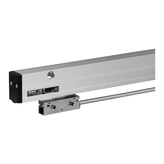
Introduction / Supplied Items SENC 125 T/E The SENC 125 T and E Precision Glass Scale Linear Encoders For future ordering information or warranty service, record the provides the accuracy and reliability of an ACU-RITE measuring linear encoder catalog number located on the scale assembly tag, ®... -
Page 5: Mounting Preparation
SENC 125 T/E Mounting Preparation SENC 125 T Please follow these preparation guide lines. • Understand your mounting requirements. • Mount with lip seals down and away from the work area. • Brackets should be kept as short and rigid as possible. “L”... -
Page 6: Mounting Information
Mounting Information SENC 125 T/E Use this information to plan your Linear Encoder Tolerances ... installation. // .010 A • Mount the linear encoders close to machine guide ways to ensure system accuracy. • If space between the reading head and the mounting surface exceeds .18”, use a mounting bracket or spacer to reduce space. -
Page 7: Encoder Dimensions - Senc 125 T (Top Mount)
SENC 125 T/E Encoder Dimensions SENC 125 T (top mounted scale case) Measuring length + 5.75 [146] [50.8] 15.75 15.75 2.0 [50.8] [400] Typ. [400] Typ. 1.72 [43.7] .28 [7.1] Mounting holes 1.25 [32] for 10-32 SHCS Min. bend rad. .95 [24.1] Ø... -
Page 8: Encoder Dimensions - Senc 125 E (End Mount)
Encoder Dimensions SENC 125 T/E SENC 125 E (end mounted scale case) Center Support Mounting hole [17.8] Measuring length + 6.55 [166.4] Measuring length + 5.44 [138.1] [14.2] Mounting hole Ø .453 C’bore Ø .313 Thru [19.0] [24.4] 2.65 .59 [14.9] [67.3] 1.25 [32] .94 [24]... -
Page 9: Encoder Center Support (For Senc 125 E Only)
SENC 125 T/E Encoder Center Support Center Linear Encoder Distance Center Linear Encoder Distance Support Measuring Length Apart Support (s) Measuring Length Apart 14.72 21.72 15.72 22.72 16.72 15.81 17.72 17.81 18.72 19.14 19.72 19.81 20.72 21.81 26.0” 26.0” 26.0” [660 mm] [660 mm] [660 mm]... -
Page 10: Mounting Requirements
Mounting Requirements SENC 125 T/E Mounting options can be adapted to machine mounting surfaces SENC 125 E M6 Flat washer x .017” thk. (2) using spacers, standoffs, leveling set screws. A spar can be used for the SENC 125 E encoder. Mounting hole cover (2) •... -
Page 11: Typical Mounting (S)
SENC 125 T/E Typical Mounting (s) Flush mounting surfaces SENC 125 T A variety of mounting conditions can be accommodated. Mounting • The machine configuration determines the brackets and surfaces flush encoder style required for installation. • Typical mounting conditions are shown; flush with reading head bracket, and SENC 125 E encoder with backup spar. -
Page 12: Encoder Installation Procedure
Encoder Installation Procedure SENC 125 T/E These steps apply to typical encoder mounting conditions and Align top of scale case to Center mounting axis within .015” of -A- assumes the mounting surface is parallel to the machine travel to -A- = Axis travel Scale case within .010”. - Page 13 SENC 125 T/E Encoder Installation Procedure Reading head bracket -A- = Axis travel Align to within .010” TIR to -A- • Attach the bracket to the reading head with the 8-32 x 5/8” BHCS. 10-32 x 1-1/4” SHCS & M5 flat washer •...
- Page 14 Encoder Installation Procedure SENC 125 T/E Connecting Secure excess cable Provide slack loops Leveling screw (3) • Place a .001”-.003” shim between the leveling set screws and mounting surface. Attach connector • Adjust each set screw until a slight drag is felt on the shim. •...
-
Page 15: Checking The Installation
SENC 125 T/E Checking the Installation These steps will confirm proper operation of your installation. Repeatability Test The counting Test confirms proper electrical operation. The Repeatability Test checks the installation integrity. Counting Test: • Configure the readout’s encoder and display resolution (see manual). -
Page 16: Electrical Shielding
Electrical Shielding SENC 125 T/E Connect a ground wire from the terminal on the back of the readout to the machine or earth ground. Attach a ground wire from the machine to a solid earth ground. With the encoder attached to the machine and the cable connected to the readout, check shielding by measuring resistance between connector housing and scale unit. -
Page 17: Troubleshooting
SENC 125 T/E Trouble Shooting If you experience difficulties with your installation, do the following Follow these steps to determine the cause of your system to determine the problem. difficulties: • Confirm that your bracketry and installation does not interfere Checking the Readout with other machine structures through the entire length of the linear encoder travel. -
Page 18: Mechanical Specifications
Mechanical Specifications SENC 125 T/E Mechanical Specifications Digital Resolution 5µm Grating pitch 20 µm Scale medium Reflectance from nickel-coated glass Accuracy (@ 20° C) ± 10µm/1000mm Max. slew speed 30 inches/sec Force required to move < 0.75 lbs reading head Operating Environment: Temperature 0°... -
Page 19: Output Signals And Pin-Outs
SENC 125 T/E Output Signals and Pin-Outs Digital Pin 1 Pin 2 Pin 3 Pin 4 Pin 5 Pin 6 Pin 7 Pin 8 Pin 9 Green Blue White Brown Pink Channel Channel Ground Vcc, + 5.1 Channel ± 0.1 VDC ACU-RITE ®... -
Page 20: Electrical Specifications
Electrical Specifications SENC 125 T/E Parameter Digital =(High level output current) = 20mA output Signals =(High level output voltage) >2.5Vdc 0° 360° Channel R+ Channel A+ 90° 1 Count Channel B+ =(Low level output current) = 20mA =(Low level output voltage) < 0.6 Vdc Incremental signals Square-wave voltage signals. -
Page 21: Warranty
SENC 125 T/E Warranty For Warranty information, go to www.acu-rite.com. ACU-RITE ® 628136-21_Ve00_SENC125T-E.indd 21 10/22/2009 1:54:26 PM... - Page 22 ACU-RITE ® 628136-21_Ve00_SENC125T-E.indd 22 10/22/2009 1:54:26 PM...
- Page 23 628136-21_Ve00_SENC125T-E.indd 23 10/22/2009 1:54:26 PM...
- Page 24 HEIDENHAIN CORPORATION 333 East State Parkway Schaumburg, IL 60173-5337 USA +1 (847) 490-1191 +1 (847) 490-3931 E-Mail: info@heidenhain.com www.heidenhain.com ACU-RITE ® 628136-21 Ver 00 • Subject to change without notice 10/2009 • 628136-21_Ve00_SENC125T-E.indd 24 10/22/2009 1:54:26 PM...
Need help?
Do you have a question about the ACU-RITE SENC 125 T and is the answer not in the manual?
Questions and answers