
Related Manuals for PSI Woodworking Products TCLC10


Summary of Contents for PSI Woodworking Products TCLC10
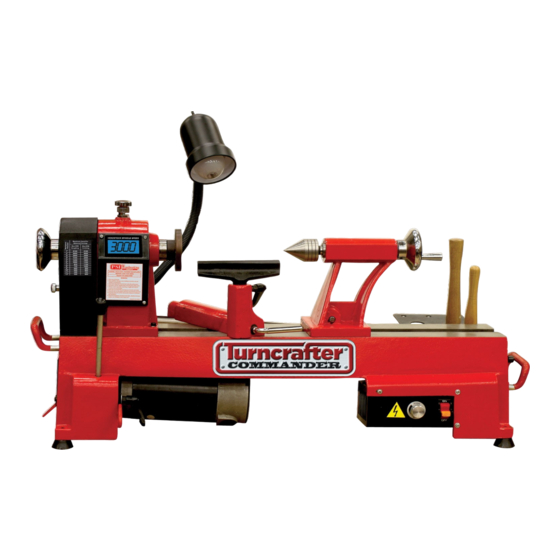
- Page 1 Turncrafter Commander Lathes User Manual (Applies to models: TCLC10, TCLC10VS & TCLC12VS) Read this manual completely before usage. Model shown: TCLC12VS www.psiwoodworkingproducts.com...
-
Page 2: Warranty
(3) years from the date of purchase. This warranty applies to the purchaser of this product, and is limited to repair or replacement of the product or it’s parts at PSI Woodworking Products’ discretion. Excluded are parts, which have been misused, abused, altered, or consumed by normal operation of the machine. - Page 3 Turncrafter Commander Specifications Turncrafter Commander 10” Swing Multi Speed 10” Swing Variable Speed 12” Swing Variable Speed Commander Commander Commander Item No. #TCLC10 #TCLC10VS #TCLC12VS Motor Speeds Single Speed 110v Variable Speed 110v Variable Speed 110v Motor Power 3/5 HP...
- Page 4 RECEIVING: 1. Remove all parts and components from shipping carton. Remove all the packing and locate all loose parts. 2. Inspect the contents of the carton for shipping damage. Compare the contents of the loose parts list provided. Report any missing or damaged parts to your distributor. 3.
- Page 5 LATHE COMPONENTS AND ASSEMBLY Lathe Assembly Components 1. Lathe Bed 15. Cord Wrapping Supports 2. Tailstock 16. Tool Holder rack 3. Hand Wheel (Quill Adjustment) 17. Knockout Rod 4. Quill Tightening Lever 18. Work Light (BULB NOT INCLUDED) 5. Live Tailstock Center 19.
-
Page 6: Control Box
GENERAL ASSEMBLY - INSTRUCTIONS 1. Install loose parts (a) - (k) as indicated in the assembly diagram above. 2. Inspect Tailstock: Verify that all knobs and handles work properly and that tailstock slide along bed and live center bearings spin freely. 3. - Page 7 Bulb not included. 3000 Pulley Positions and Speeds Remove the belt cover (29). Loosen motor racket handle (10). Move belt to speed position as indicated in illustration below. TCLC10 Multi Speed TCLC10VS, TCLC12VS Speeds RPM Spindle TCLC10...
-
Page 8: Spur Center
USE OF INDIVIDUAL COMPONENTS Powering the Lathe: The power switch (12) controls the flow of power to the motor. Toggling the switch to the ON position will start the mo- tor. The lathe will begin turning and reach its full speed within a few seconds. The time the motor takes to reach its full speed will depend on the size of the work piece and the speed setting. -
Page 9: Recommended Turning Speeds
RECOMMENDED TURNING SPEEDS WARNING. Turning too fast for the size of your work may result in injuring yourself or damaging the lathe! Chart for TCLC10VS & TCLC12VS Multi Speed Chart for TCLC10 Maximum Speeds for Balanced Turnings Max work Max Speed piece dia. - Page 10 TYPICAL LATHE OPERATIONS Spindle Turning • Work mounted between headstock spur center and live tailstock center • Requirements: no additional accessories • Optional headstock mounting with lathe chuck Bowl Turning • Mount work to faceplate with screws • Requirements: no additional accessories •...
- Page 11 Accessories Available From Psi Woodworking Products For Your Commander Lathe Item Description Typical Products Lathe Extension Bed Extends the lathe and Spindle you can turn to 42” #TCLC10XB for 10” Styles #TCLC12XB for 12” Style Duplicating Attach- Enables duplicating small projects to 9” long.
- Page 12 10” & 12” Variable Speed Models TCLC10VS and TCLC12VS Part List...
- Page 13 Part No. Description Part No. Description Washer Ø8 Hex socket screw M10x25 Drive pulley Washer Ø10 22-1 Hex socket taper screw M6x12 Handle Side protection guard Retaining ring 10 Hand wheel Quill adjusting wheel 24-1 Hex socket screw M6x12 Bush Side plate Screw 25-1...
- Page 14 TCLC10 Part List...
- Page 15 Part No. Description Part No. Description 30-4 Screw Quill adjusting wheel Toolrest Bush Toolrest base Screw Bush Hex socket screw M6x12 Lock handle for tool rest base Tailstock 34-1 Retaining ring 10 Cam follower tailstock Handle Eccentric axis 35-1 Lock bolt Retaining ring 10 35-2 Spring...
- Page 17 ASSEMBLY OF TCLC12VS VARIABLE SPEED LATHE second contains the headstock assembly, toolrest and tailstock assembly. The parts shown below: Headstock Assembly Tailstock Assembly Handwheel* Indexing Knob* Belt Cover Toolrest(s)* Maximum RPM Finishing 4100 1” 4100 4000 2” 3000 2000 2600 3”...
- Page 18 Connecting the Motor to the Board Connection in Headstck Lead from Motor TCLC12VS Assembly - 10/10 v2...
- Page 19 ©2010 PSI Woodworking Products V.510...
Need help?
Do you have a question about the TCLC10 and is the answer not in the manual?
Questions and answers