Porsche PCM Installation And Conversion Instructions
Navigation module with standard audio interface + dvd autochanger for cayman 981
Hide thumbs
Also See for PCM:
- Compatibility and connection (51 pages) ,
- Compatibility and connection (55 pages) ,
- Manual (34 pages)
Advertisement
Quick Links
Installation and Conversion Instructions
PCM incl. Navigation Module with Standard Audio Interface + DVD Autochanger
Revision:
This bulletin replaces bulletin Group 9 24/13, dated September 12, 2013.
As of 2013
Model Year:
Information:
Retrofitting
Restriction
•
Only together with Sound Package Plus (I-no. 490) or Bose® Surround Sound System (I-no. 680) or
Burmester® High-End Surround Sound System (I-no. 682).
Note:
The PCM3.1 Navigation/DVD Auto Changer retrofit is currently not for cars with XM Satellite Radio. If the
PCM3.1 Navigation/DVD Auto Changer is retrofitted in these cases, the customer will permanently lose
their XM Satellite Radio functionality. In addition, when the PCM3.1 Navigation/DVD Auto Changer retrofit
is installed in a Cayenne which previously did not have the navigation option (either CDR31 or PCM3.1
without navigation), the map display screen will not be shown on the cluster TFT, as compared to PCM3.1
Navigation units configured from the factory. This is due to a difference in instrument clusters between
factory navigation and non-navigation vehicles.
Information:
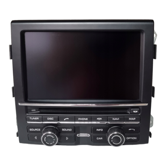
PCM incl. navigation module with standard audio interface + DVD autochanger has the following
equipment and functions:
•
Central multimedia system with 7-inch TFT color display (touchscreen).
•
Radio with RDS diversity function.
•
Integrated 6-slot CD/DVD autochanger for audio playback of audio/video DVDs and MP3 music.
Tequipment
Cayman (981)
24/13
9110
ENU
Mar 31, 2022
Page 1 of 30
9
Advertisement

Related Manuals for Porsche PCM


Summary of Contents for Porsche PCM
- Page 1 Navigation units configured from the factory. This is due to a difference in instrument clusters between factory navigation and non-navigation vehicles. Information: PCM incl. navigation module with standard audio interface + DVD autochanger has the following equipment and functions: •...
- Page 2 If the vehicle is equipped with the audio system CDR Plus, it is only a matter of routing the GPS antenna line, installing the GPS antenna, coding PCM and loading the navigation data (Steps 1 – 3 and 6 – 9).
- Page 3 You can generate the enabling code in the PIWIS information system yourself using the supplied license key (see section 1.1). You can then load the country database (PCM 3.0/PCM 3.1 navigation database ..) and the relevant workshop DVD onto the PCM 3.1 hard drive.
- Page 4 9818 - PIWIS Tester II Tools: T10118 - Assembly tool Block diagram: Information For a better understanding of the system layout, see system diagram , Figure 3. Figure 4 – PCM – GPS antenna line Mar 31, 2022 Tequipment Page 4 of 30...
- Page 5 – 3-pin connector – BCM control unit, front Work Procedure: 1 Preparatory work. Generate the PCM navigation map material enabling code in the PIWIS information system. Select the following windows one after the other: 1.1.1 Vehicle identification → Identification via VIN Enter the chassis number in the Identification via VIN field and then select Vehicle...
- Page 6 Enter the license key in the input field Generate enabling code Figure 5 -1-. Activate the Check license key field Figure 5 -2- by clicking with the mouse. 1.1.3 Generate PCM code. Mar 31, 2022 Tequipment Page 6 of 30...
- Page 7 A message also appears informing you that the licence key can only be used once and is then unusable Figure 6 -4-. Activate the field Generate PCM code Figure 6 -5- by clicking with the mouse. Take note of the displayed enabling code Figure 7 -6-.
- Page 8 Installation and Conversion Instructions 24/13 9110 Figure 7 1.1.5 Select and take note of the enabling codes for PCM Navigation, PCM UAS (standard audio interface) and PCM Bluetooth, PCM Sport Chrono MMI and DAB if necessary. Connect a battery charger.
- Page 9 Cayman (981) Installation and Conversion Instructions 24/13 9110 Remove covers Figure 8 -B- over the interior rear-view mirror. Workshop Manual '682719 Removing and installing interior rear-view mirror' Remove right sun visor. Workshop Manual '682319 Removing and installing sun visor' Remove holder for sun visor at the left and right.
- Page 10 Cayman (981) Installation and Conversion Instructions 24/13 9110 1.7.2 Unscrew fastening screw securing sun visor holder Figure 10 -arrow-. Remove centre roof trim panel. Workshop Manual '708319 Removing and installing front roof trim panel' Remove A-pillar trim panel on the right. Workshop Manual '705719 Removing and installing A-pillar trim panel' Information...
- Page 11 Figure 14 -arrows b-. Route GPS antenna line as follows: Front roof trim panel → along wire harness for sun visor → A-pillar → along wire harness for dashboard (glove compartment) → PCM installation slot Figure 14 Mar 31, 2022 Tequipment...
- Page 12 Cayman (981) Installation and Conversion Instructions 24/13 9110 Information Make sure that the roof cover does not buckle. Carefully pull down the headliner and route antenna line Figure 15 -1- along the standard wire harness for the sun visor and A-pillar.
- Page 13 Figure 18 -1- to the PCM central connector. Figure 18 The GPS antenna line Figure 19 -1- must protrude approx. 7 cm beyond the PCM central connector Figure 19 -2-. – 7 cm Figure 19 Clip three clip-on tie-wraps ...
- Page 14 Cayman (981) Installation and Conversion Instructions 24/13 9110 Route USB line Figure 21 -1- along the standard AUX line Figure 21 -2- and secure it with a tie-wrap. Convert adapter for audio interface. Figure 21 4.2.1 Release adapter close to the ...
-
Page 15: Table Of Contents
Cayman (981) Installation and Conversion Instructions 24/13 9110 Fit fastening part Figure 24 -1- on short bar of the antenna control unit Figure 24 -2-. Figure 24 Convert antenna lines (antenna control unit to antenna amplifier). Figure 25 ... -
Page 16: Figure 27
Cayman (981) Installation and Conversion Instructions 24/13 9110 5.2.2 Lift up the locking mechanism Figure 27 -1- and carefully pull the antenna line (thinner line) out of chamber 2 Figure 27 -arrow-. Figure 27 5.2.3 Insert the antenna line you pulled out into the grey antenna connector and press down the locking mechanism... -
Page 17: Antenna Amplifier)
Connect antenna lines (according to colour coding) and power supply line to the antenna control unit. – Antenna lines (antenna control unit to antenna amplifier) – Antenna line (PCM to antenna control unit) – Power supply line – 3-pin connector – Antenna connector, curry –... - Page 18 Cayman (981) Installation and Conversion Instructions 24/13 9110 5.5.2 Disconnect plug connections for door connection point Figure 32 -1- and plug connections for wire harness for dashboard Figure 32 -2-. Figure 32 Release plug connection Figure 33 -arrow a- and pull off connector ...
- Page 19 Cayman (981) Installation and Conversion Instructions 24/13 9110 Avoid small bending radii when routing lines. File down edges and burrs in the routing area or mask them with adhesive tape. Maintain a sufficient distance from components exposed to high temperatures while driving. Install antenna control unit.
- Page 20 Figure 37 -arrow a- to remove it. Figure 37 5.8.2 Route antenna line (antenna control unit to PCM) and power supply wire harness (antenna control unit) Figure 38 -1- to the PCM installation slot. Antenna control unit → fuse box →...
- Page 21 Cayman (981) Installation and Conversion Instructions 24/13 9110 Route antenna line and power supply wire harness to the PCM central connector. – Antenna line (antenna control unit to PCM) – Power supply line (antenna control unit) Figure 40 5.8.3 Pull standard antenna lines off the antenna amplifier.
- Page 22 Figure 44 Join WH line from the power supply wire harness for the antenna control unit to the line from chamber A14 Figure 45 -1- of the PCM central connector. Figure 45 Mar 31, 2022 Tequipment Page 22 of 30...
-
Page 23: Release Secondary Lock
Cayman (981) Installation and Conversion Instructions 24/13 9110 5.9.1 Release secondary lock Figure 46 -1- on the PCM central connector Figure 46 -2- ( Figure 46 -arrow A-) and pull it out Figure 46 -arrow B-. -
Page 24: Figure
Figure 49 -arrow-. Figure 49 5.10 Secure the standard double connector Figure 50 -1- to the PCM wire harness Figure 50 -2- with wrapping tape. Figure 50 5.11 Insert fuse box into the guide on the holder ... - Page 25 Figure 53 Manual '681519 Removing and installing glove compartment' Information It is more difficult to push the PCM system into the installation slot due to the additional antenna lines. Install PCM. Workshop Manual '911019 Removing and installing PCM display and...
- Page 26 Once the vehicle handover log has been created, press •F11“ to return to the list of control units. Write basic coding from PCM. 7.4.1 Select the PCM/CDR control unit and switch to the Maintenance/repairs menu. Select Control unit replacement. Press •F12“ to continue. 7.4.2 Select Write data mode. Press •F12“ to continue.
- Page 27 Installed cell, the tick disappears. Select coding value 693 - Integrated autochanger (DVD). When you touch the Installed cell, a tick appears. Select coding value 696 - CD radio “Porsche CDR 31” WW. When you touch the Installed cell, the tick disappears. 7.5.4 Only for vehicles with audio system CDR Plus: Select coding value, e.g.
- Page 28 Select Automatic coding mode. Press •F12“ to continue. Wait until the message Coding has been completed successfully appears. Press •F12“ to continue. Check the chassis number in the PCM control unit. Switch to the Extended identification menu. Check the chassis number and 7.7.1 change it if necessary.
- Page 29 DVD onto the PCM hard drive. Save navigation data to the PCM hard drive. Switch on ignition and insert the “PCM 3.0/PCM 3.1 Navigation Database XYZ” DVD in the CD/DVD slot. Confirm the message: “Avoid interrupting the update process. Interrupting the update can result in malfunctions in the PCM system.”...
- Page 30 Technical Bulletins issued by Porsche Cars North America, Inc. are intended only for use by professional automotive technicians who have attended Porsche service training courses. They are written to inform those technicians of conditions that may occur on some Porsche vehicles, or to provide information that could assist in the proper servicing of a vehicle. Porsche special tools may be necessary in order to perform certain operations identified in these bulletins.
Need help?
Do you have a question about the PCM and is the answer not in the manual?
Questions and answers