
Subscribe to Our Youtube Channel
Related Manuals for WEICHAI BAUDOUIN PowerKit 16M33 Series


Summary of Contents for WEICHAI BAUDOUIN PowerKit 16M33 Series
- Page 1 张安勇/Zhang Anyong 宋安泽 王巧荣 于千钧 于千钧 许太法 林世龙 20200425 “1005098300 - Operation_and_Maintenance_Manual_for_PowerKit_16M33_Series_Gas_Engine, A”...
- Page 2 Operation and Maintenance Manual for PowerKit 16M33 Series Gas Engine OMMBV2003 张安勇/Zhang Anyong 宋安泽 王巧荣 于千钧 于千钧 许太法 林世龙 20200425 “1005098300 - Operation_and_Maintenance_Manual_for_PowerKit_16M33_Series_Gas_Engin...
-
Page 3: Foreword
Foreword Foreword Please be advised, do not operate or basic safety precautions shows perform any operation, maintenance, or warnings potentially hazardous repair on this PowerKit engine until you have situations. This Manual must be read in full read and understood the information in this before operating your PowerKit in order to Manual in its entirety. -
Page 4: Table Of Contents
Content Foreword ..........................3 1. Safety ..........................6 1.1 Safety Information ......................6 1.2 Symbols Used ......................7 1.3 Personal Safety ......................10 1.4 Environmental Safety ....................10 1.5 Fluid Safety ......................... 11 1.6 Batteries ........................11 1.7 Welding ........................12 1.8 Electrical Risks ...................... - Page 5 Content 5.3 Maintenance Operations .................... 62 5.4 Storage Protection Instruction ..................80 6. Appendix ........................90 6.1 Coolant Recommendation ..................90 6.2 Lubricant Recommendation ..................91 6.3 Fuel Recommendation ....................93 6.4 Special Tools Recommendation ................. 94 6.5 Common Faults and Troubleshooting ................ 97 6.6 Maintenance Log ......................
-
Page 6: Safety
Safety 1. Safety 1.1 Safety Information Failure to comply with the preventive measures and safety instructions included in this manual and with warnings indicated on the engine may lead to injury or death. This Operation and Maintenance Manual must be kept on or near the engine and must be easily accessible and ready to be consulted at any time. -
Page 7: Symbols Used
Safety 1.2 Symbols Used Please take note of the warnings and precautions indicated throughout this Manual in order to avoid unsafe practices and conditions. In this Manual, the following symbols are used to highlight specific information. HAZARD WARNING This warning symbol is recognized across the world. - Page 8 Safety Safety symbols Symbol Definition Wear hand protection Wear ear protection Wear eye protection Wear head protection Wear foot protection Wear a protective mask Wear overalls Avoid naked flames Do not smoke Do not use a mobile phone Keep an extinguisher close by Danger: battery acid Danger: live cables, electrical risks Highly flammable products...
- Page 9 Safety Universal Warning The location of the Universal Warning label is illustrated below. 16M33 Gas Engine Series Figure 1.2B-16M33 Gas Engine Illustration Do not operate or perform maintenance on this engine unless you have read and understand the instructions and warnings in this Operation and Maintenance Manual.
-
Page 10: Personal Safety
Safety 1.3 Personal Safety These Personal Safety precautions are designed to reduce the risk of contamination, serious injury or death. Wear personal protective equipment (PPE) as required. Avoid prolonged and repeated contact with oil. Do not put oily rags in pockets. ... -
Page 11: Fluid Safety
Safety 1.5 Fluid Safety All oil, natural gas, and some coolant liquids are flammable. If these liquids and gas are leaking onto hot surfaces they can cause a fire which can cause injury and/or damage. Do not check for leaks using any body part. -
Page 12: Welding
Safety The battery cables must be fitted with a battery switch and fuse or circuit breaker to isolate the circuit. Sulphuric acid contained in batteries is toxic and corrosive; it can burn clothes and skin or even cause blindness in case of contact with the eyes. -
Page 13: Electrical Risks
Safety before welding (control cabinets, electrical cabinets etc.). Comply with all legal provisions in force before conducting welding work. Do not use open fires. Make sure that the work will not affect the on-board electrical and electronic equipment. -
Page 14: Lines, Tubes And Hoses
Safety Flexible connections for cooling Flexible circuit connections fuel Electrical control systems and electronic fuel injection Earth faults can cause corrosion in the pipes and engine or genset unit compo- nents. 1.9 Lines, Tubes and Hoses ... -
Page 15: Cleaning The Engine
Safety Slowly unscrew the coolant filler plug to release pressure. 1.11 Cleaning the Engine Use personal protective equipment when cleaning an engine. Regularly clean the engine surface to remove any greasy deposits that may be flammable. Do not wash an engine in operation or which has just stopped. -
Page 16: General Precautions For Operation
Safety 1.12 General Precautions for Operation 1.12.1 Before any operation or maintenance on any Baudouin product Wear personal protective equipment (PPE) where required. For maintenance, place a “Do Not Use” or similar sign on the starter switches. Access to the equipment is only for authorized and qualified personnel. - Page 17 Safety 1.12.2 Starting the Engine For initial start-up of a new engine, or the first start after a service, make provisions to be able to stop the engine if a fault occurs. This can be done by shutting off the gas or air supply to the engine.
-
Page 18: Product
Product 2. Product 2.1 Rating Definitions Rating definitions Running conditions Annual running time is unlimited. Continuous rated power is allowed. Continuous power No overload ability. Annual running time is unlimited. The average load rate is no more than 70% during a range of 24 hours. -
Page 19: Engine Model
Product 2.2 Engine Model 2.2.1 Meaning of Engine Model 2.2.1.1 Product Model of Baudouin Industrial Engine 2.2.1.2 Product Series Code Product series Code is comprised by Cylinder Number、Product Code for Baudouin (M) and Displacement per Cylinder. 2.2.1.3 Application Code Code Application Land Power Generation Land Power Generation for Tele com... - Page 20 Product 2.2.1.5 Speed Code 3000 1500 1800 1500 & 1800 Code Engine speed is only used for gen-set application using, and is shown as table, the speed code for other application will not be used. 2.2.1.6 Emission Stage Codes Emission Stage Code Non-road No emission certification U.S.
- Page 21 Product 2.2.2 Engine Plate 16M33 Series Gas engine Figure 2.2.2A-16M33 Gas Engine Plate Position 张安勇/Zhang Anyong 宋安泽 王巧荣 于千钧 于千钧 许太法 林世龙 20200425 “1005098300 - Operation_and_Maintenance_Manual_for_PowerKit_16M33_Series_Gas_Engin...
-
Page 22: Engine Overview
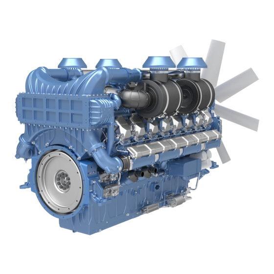
Product 2.3 Engine Overview 2.3.1 Schematic Diagrams of 16M33 Gas Engine 1-Water Outlet Pipe 2- Turbocharger 3-Mixer of Gas and Air 4-Intercooler 5-Ignition Coil Starter 7-Centrifugal Oil Filter 8-Oil Cooler 9-Oil Filter 10-Low Temperature Water Pump 11-Alternator 12- Water Thermostat Figure 2.3.1A-Right Side 13-Air and Gas Intake Manifold... -
Page 23: Cooling Circuits
Product 2.4 Cooling Circuits 16M33 series gas engine is equipped with 2 cooling circuits. High temperature cooling circuit to cool: Cylinder block and cylinder head Turbocharger Engine oil through oil cooler The internal circuit is designed for self-degassing. To provide effective engine protection against freezing, chemical and galvanic corrosion, cavitation and depositing, it is IMPERATIVE to use the recommended coolant as defined in the 6.1 Coolant Recommendation. - Page 24 Product 2.4.2 Low Temperature Cooling Circuits for 16M33 Series Gas Engine Overall Layout 1- Radiator 2- Low-temp Water pump 3- Cooled Water Line 4- Intercooler 5-Water Back to Radiator Figure 2.4.2-Overall Layout of low-temp cooling circuits 张安勇/Zhang Anyong 宋安泽 王巧荣 于千钧...
-
Page 25: Lubrication System
Product 2.5 Lubrication System 16M33 Series gas engines are equipped with a lubrication system including two oil coolers. The gear driving oil pump is located at the low front of the engine. Many engine parts are lubricated by pressurized oil through piping and crankcase hoses. ... -
Page 26: Gas Supply System
Product 2.6 Gas Supply System 2.6.1 Gas supply diagrams of 16M33 gas engine The gas source provides gas meeting the standard of Chapter 6.3 Fuel Recommendation. The gas (50-100KPa) goes through gas filter, shut-off valve, and pressure reducer in turn. The mixer mixes natural gas and air in proportion controlled by ECU (Engine Control Unit). - Page 27 Product 2.6.2 Main Parts of Gas supply system Gas filter Function description: Filter the impurities in the gas. Technical parameters: Inlet pressure: (0~2)bar; Working temperature: : -20℃~70℃; Filter radius:50μm. Figure2.6.3-Gas Filter Shut off valve Function description: Cut off or restore gas supply, it is the safety protection switch on the gas pipeline.
- Page 28 Product Gas and air mixer Function description: The gas and the air after filtration are fully mixed to make the combustion more fully and soft, effectively reducing the NO emission and exhaust temperature. Figure2.6.4-Gas and Air Mixer 张安勇/Zhang Anyong 宋安泽...
-
Page 29: Electronic Control Unit (Ecu) And Electronic Parts Introduction
Product 2.7 Electronic Control Unit (ECU) and Electronic Parts Introduction Function description: ECU collects inlet manifold pressure (MAP), inlet manifold temperature (MAT), engine phase, revolving speed, outlet water temperature, exhaust oxygen concentration and other signals and controls the action of electronic throttle, ignition timing and ignition orders after calculation so as to accomplish electronic control of engine. - Page 30 Product Camshaft signal sensor Function description: Camshaft signal sensor is mainly used for ECU to get exactly the camshaft position engine‟s revolving speed. Engine control unit (ECU) uses revolving speed to control many parameters, including air input, ignition advance angle, etc.
- Page 31 Product Engine speed sensor Function description: Engine speed sensor is mainly used to measure engine‟s revolving speed. We can use it to compare with engine‟s revolving speed of Camshaft signal sensor. By this way, engine working will improve stability and reliability.
- Page 32 Product Ignition coil Function description: This system adopts independent cylinder ignition coil, ECU controls coil‟s charging hours, charging time and discharging hours engine charge current shall maintained at 6.5A under any conditions. Figure2.7.8-Ignition coil Ignition cable Function description: Ignition cable is used to transmit high pressure spot generated by ignition coil to sparking plug so as to generate electric...
-
Page 33: Installation
Installation 3. Installation Safety instructions Users should carefully read and fully understand the safety instructions before installing and operating the gas engine. The purpose of the installation instructions is to: Provide insight and advice in installing your engine. Establish proper conditions for no trouble operation. -
Page 34: Engine Lifting
Installation 3.1 Engine Lifting 3.1.1 Lifting device Always use the lifting device to lift the very heavy parts that is unsuitable for carrying by hand. Check the lifting device status regularly such as hook and chain. Do not use unsafe tools. Do not use the tools before you are familiar with it. 3.1.2 Lifting the engine The 16M33 gas engine's net weight is approx.5500Kg. - Page 35 Installation The four lifting eyes of 16M33 series gas engine are illustrated as following: Figure 3.1.3 A - Right lifting eyes (face to the flywheel) Figure 3.1.3 B - Left lifting eyes (face to the flywheel) 张安勇/Zhang Anyong 宋安泽 王巧荣 于千钧...
- Page 36 Installation Figure 3.1.3 C – Distance between left lifting brackets and right lifting brackets 张安勇/Zhang Anyong 宋安泽 Figure 3.1.3 D – Dimensions of lifting bracket 王巧荣 于千钧 于千钧 许太法 林世龙 20200425 “1005098300 - Operation_and_Maintenance_Manual_for_PowerKit_16M33_Series_Gas_Engin...
-
Page 37: Engine Mounting
Installation 3.2 Engine Mounting In order to ensure the installation durability, pay attention on the following criteria: All the engine's mounting brackets should be used Vibration absorber should be arranged to reduce vibration from the engine to its chassis. For the engine's installation angle: ... -
Page 38: Accessories
Installation Figure 3.2 B -Left bracket 3.3 Accessories In order to ensure engine durability and performance, the accessory installation must meet the following criteria: Add O-ring seal during installation in the coolant system pipes. As the figure 3.3, the O-ring should be arranged in the flange before it was connected to the radiator outlet pipe. -
Page 39: Air Intake System
Installation 3.4 Air Intake System If the gas engine is without the air filter, operator should fit the air filters and filter status indicator. The air intake system must avoid the followed material entry into it: Water or rain. ... -
Page 40: Lubrication System
Installation Figure 3.6 - Vibration absorber arrangement If the engine works in a soundproof box, sealing rubber should be installed around the radiator to prevent the hot air beyond the engine from flowing back into the cool air entrance. ... - Page 41 Installation For the pressure of the gas out of the gas pressure reducer, the value should be in 50mbar~130mbar. 3.8.1 Gas line The lines installed before the gas pressure reducer should be the tough line, also the flange or the threaded line can be used to connect. ...
-
Page 42: Engine Electronic System
Installation 3.8.3 Gas pressure reducer The proper working temperature for the regulator is -15℃~70℃. The distance from the reducer to the engine should be ≤2m. The regulator vibration level should be lowest. The regulator should be installed after the filter. ... -
Page 43: Engine Electronic Controlling System
Installation 3.9.2 Charging Circuit The charging cable shall be a complete cable without intermediate connector; Terminals of B+/D+/W shall be provided with protective caps; Permissible voltage decrease on charge cable≤1V; The schematic diagram of the alternator wiring is as follows: Figure 3.9.2 - Alternator wiring diagram 3.10 Engine Electronic Controlling System 3.10.1 ECU wire connection... - Page 44 Installation The cross-sectional area of the wire is 0.75mm Figure 3.10.1 B-Key switch for "ignition" "run/stop switch" wire Pin No.:J1-46. Functional description: Turning on allows the engine to start and the throttle and TecJet™ work properly. When disconnected, the throttle and TecJet™ are always closed.
- Page 45 Functional description: The automatic speed control function is generally used in control systems that require automatic parallel or grid connection. Currently, the Weichai gas system supports two forms of signal input. A hard-wire signal input receives the GOV speed-regulating voltage signal of the 张安勇/Zhang Anyong...
- Page 46 Installation speed-regulating center point voltage is 2.5V, the speed-regulating voltage The range is ±2V and the engine speed is 1500±90rpm. The other is connected to the ECU's CAN bus through the parallel or grid-connected controller. By sending a GC2 message conforming to the J1939 protocol to the ECU, the ECU receives the message and responds to the target speed.
- Page 47 Installation Figure 3.10.1 G- Wire for "generator breaker switch" CAN bus function Pin No.: J2-7(CAN2_H), J2-8(CAN2_L), J2-16(Shield). Functional description: CAN2 is used for troubleshooting or communication with other CAN instruments. Wiring is required for twisting, and 120Ω terminating resistor is integrated in the ECU. ...
-
Page 48: Gen Set Installation Recommendation
Installation 3.11 Gen Set Installation Recommendation Installer must choose the proper location in order to avoid noise pollution. If the location is not proper, enclosure has to be used for noise reduction. Also, the proper exhaust silencer must be used if necessary. ... -
Page 49: Operation
Operation 4. Operation The first engine commissioning process should be handled by S. I. Moteurs Baudouin ap- proved personnel. The successful completion of this process, along with the checks and adjustments required by S. I. Moteurs Baudouin, will ensure that the engine runs efficiently, reliably, and safely. -
Page 50: Preparations Before Start
Operation 4.1 Preparations before Start Adding of engine oil Open the oil filler cap and add the engine oil. Using the dipstick to check the oil level. Natural Gas Figure 4.1A-Adding of engine oil Adding of the natural gas ... - Page 51 Operation Notice! After the genset is installed in site, please make sure must remove long adjustment bolts bellows before starting the genset. 张安勇/Zhang Anyong 宋安泽 王巧荣 于千钧 于千钧 许太法 林世龙 20200425 “1005098300 - Operation_and_Maintenance_Manual_for_PowerKit_16M33_Series_Gas_Engin...
-
Page 52: Starting Up
Operation 4.2 Starting Up The following starting/stopping procedure is a simple example (not binding) and it‟s based on a simple starting control panel equipped with starting key. Please refer to the genset and/or genset control panel use & maintenance manual for the starting operation mode. ... -
Page 53: Operation Of The Powerkit Engine
Operation 4.3 Operation of the PowerKit Engine After the start of engine, idle the engine for 3min, and then increase the speed to 1000r/min to 1200r/min with some load. Only when the coolant temperature is above 60º C and the oil temperature is above 50º C, can the engine run with full load. The load and speed should be increased gradually. -
Page 54: Precautions For Running In Cold Environments
Operation 4.4 Precautions for running in cold environments Lubricating oil: Choose lubricating oil of different viscosities depending on the seasons. Coolant: Add antifreeze additive into the cooling system and choose the coolant of differ- ent grades depending on the ambient temperature. ... -
Page 55: Stopping The Powerkit Engine
Operation 4.5 Stopping the PowerKit Engine Avoid shutting down the engine at full load. Before the shut-down, engine load and should be reduced, and the engine should operate at low-load condition for 3 to 5 minutes. This allows the piston, cylinder head, liner, bushing and turbocharger to cool down, avoiding cylinder and bearing damage. -
Page 56: Electronic Control System
Operation 4.6 Electronic control system Reading the fault code via the diagnostic switch: Press the diagnostic switch (diagnostic lamp comes on), and then release to reset the diagnostic switch (diagnostic lamp turns off) The diagnostic lamp flashes and reports the fault code ... -
Page 57: Maintenance
Maintenance 5. Maintenance 5.1 General Safety Conditions for Maintenance SAFETY WARNING Users should carefully read the safety instructions before installation and operation of the engine. Safety conditions for preventive and corrective maintenance operations are intended to check. Engine and generator alignment. ... -
Page 58: Maintenance Table
Maintenance 5.2 Maintenance Table MOTEURS BAUDOUIN • Check = In operation hours or period, every. о Adjust = Hours and Months: A first-come-prevail. Δ Clean = □ Replace = Hour 1500 2250 3000 6000 OPERATION Month • The coolant level •... - Page 59 Maintenance MOTEURS BAUDOUIN • Check = In operation hours or period, every. о Adjust = Hours and Months: A first-come-prevail. Δ Clean = □ Replace = Hour 1500 2250 3000 6000 OPERATION Month □ Engine oil □ Oil cartridges Δ/□ The air filter Condensing draining...
- Page 60 Maintenance MOTEURS BAUDOUIN • Check = In operation hours or period, every. о Adjust = Hours and Months: A first-come-prevail. Δ Clean = □ Replace = Hour 1500 2250 3000 6000 OPERATION Month Battery, battery electrolyte level, • battery charger, battery cables Tightness of hoses and hose •...
- Page 61 Maintenance MOTEURS BAUDOUIN • Check = In operation hours or period, every. о Adjust = Hours and Months: A first-come-prevail. Δ Clean = □ Replace = Hour 1500 2250 3000 6000 OPERATION Month • Coolant pump • Gas shutoff valve •...
-
Page 62: Maintenance Operations
Maintenance 5.3 Maintenance Operations 5.3.1 Maintenance Operations NOTE! Before performing any maintenance work, the engine must be turned off and have cooled off, the battery main switch must be switched off and the ignition key removed, put ‘Do not start the engine’ sign aside the gen-set. ... - Page 63 Maintenance Remove coolant filler cap. Figure 5.3.1.B Slowly fill coolant until the coolant higher than the min. mark. For the first time filling, the air should be released thoroughly. After the air is released thoroughly, fill the coolant until its level higher than min.
- Page 64 Maintenance Close cap. Run engine for apporx.15 minutes at rated speed. Check the coolant level gauge. If it is need to fill, shut off engine and carefully unscrew cap with safety valve to the first stop to release pressure.
- Page 65 Maintenance Check the oil level NOTE! Check the oil level when the engine is horizontal at idle speed or engine stopped. If check the oil level when engine stopped only after at least 20 minutes have passed since the engine was switched off. ...
- Page 66 Maintenance Check the belt NOTE! The belt is automatically tensioned with a tensioner. Slippage of loose belts can reduce the efficiency of the driven components. Vibration of loose belts can cause unnecessary wear on the following components: Belts, pulleys and bearings.
- Page 67 Maintenance Check the exhaust gas color During the normal running of gas engine, the color of exhaust air is light grey. When the color changes, check the cause and do troubleshooting. Figure 5.3.1.M Check the air cleaner service indicator (if equipped). ...
- Page 68 Maintenance Check if the vibration is in normal condition, and if the speed is stable. NOTE! The abnormal vibration and unsteady speed can cause serious damage to your engine. When there is this type problem, stop your engine and inspect. ...
- Page 69 Maintenance Replace the engine oil Note! Be careful when draining hot engine oil. Hot engine oil can cause burns to un-protected skin. Comply with applicable rules and regulations for the work place. Obey environmental regulations for the disposal of used oil. To perform this operation with warm engine, to get a better fluidity of the oil and get a full discharge of oil and impurities contained it.
- Page 70 Maintenance Check the oil level after finished; refer to “Engine oil check”. And retighten the lubricant oil cap. Start engine and let it run at slow idle for 1 minute. Check for oil leaks at engine oil filter. Tighten only enough to stop leaks.
- Page 71 Maintenance Change the air filters Release clamp (2). Remove air filter (3) and clamp (2) from flange of intake housing (1). Verify that there are no objects in the flange of the intake housing (1) and clean it. ...
- Page 72 Maintenance Clean the gas filter Note! If the cleaning quality of local gas source is poor, please shorten the cleaning interval appropriately. After making sure there is no gas in the filter, remove the filter net (number 2), wash with soapy water, and air dry naturally, reinstall the filter net.
- Page 73 Maintenance Clean the oil-gas separator element For 16M33NG engine, there are two separators, after removing the bolt (1), cover (2), stud bolt (3), , can remove the filter cartridge (4). Figure 5.3.2.A Clean the breather cartridge with fuel.
- Page 74 Maintenance Clean the radiator and cooling system Clean radiator cooling fins with compressed air. Cleaning should done always opposite direction of air flow. Figure 5.3.2.D Replace the spark plug Spark plug clearance adjustment Adjustment method: If the clearance is wide, insert the feeler gauge into the clearance, and tap the corner of the side electrode gently with a small...
- Page 75 Maintenance Check the rocker arm and cross-bar clearance ! Note Ensure that the engine can’t be started while this maintenance is being performed. To help prevent possible injury, do not use the starting motor to turn the flywheel. Hot engine components can cause burns. Allow additional time for the engine to cool before checking/adjusting valve system clearance.
- Page 76 Maintenance 5.3.2 Overhaul Operations 5.3.2.1 Overhaul Information An overhaul is replacing the major worn components of the engine. An overhaul is a maintenance interval that is planned. The engine is rebuilt with certain rebuilt parts or new parts that replace the worn parts. An overhaul also includes the following maintenance: ...
- Page 77 Maintenance Rebuild Replace Turbocharger Cylinder head assemblies Coolant pump Starter Replace Valve bridge Ignition cable assembly Rocker arm The fan bracket Rocker arm shaft Belt tensioner Unexpected problems may be found during a top overhaul. Plan to correct these problems, if necessary.
- Page 78 Maintenance Those components are replaced, if necessary. The recommendations of parts for in-structure overhaul is as followed: Clean The lubricating pipes (rocker arm, Gas Mixer turbochargers) Clean Inspect Test Intercooler Oil cooler Gas reducer Throttle ...
- Page 79 Maintenance A major overhaul includes all of the work that is done for top overhauls and structure overhauls. A major overhaul includes additional parts and labor. Additional parts and labor are required in order to completely rebuild the engine. In some cases, the engine is relocated for disassembly. For the major overhaul, all of the bearings, seals, gaskets, and components that wear are disassembled.
-
Page 80: Storage Protection Instruction
Maintenance Push rod and tappet inspect Take out the push rod and check whether there is lubricating oil flowing from the ball socket of the push rod out, whether there is lubricating oil attached to the side, if there is less lubricating oil, we need to check whether the oil line of the rocker arm and rocker arm shaft is obstructed. - Page 81 Maintenance cracks in the cylinder head, a piston seizure or other potential damage to the engine. Visually inspect the water pump for leaks. If leaking of the water pump seals is observed, replace all of the water pump seals. Refer to the repair manual. Inspect the water pump for wear, cracks, pin holes and proper operation.
- Page 82 Maintenance Electrical Pre-lubricating Pump Inspect the pre lube pump for the following conditions: Cracks Pin holes Proper operation Wear Inspect the pre lube pump for leaks. Replace all of the seals if a leak is observed. Inspect all of the components in the electric circuit for the pre lube pump.
- Page 83 Maintenance Test There should be no leakage in one minute with 0.35Mpa compressed air blown in the intercooler. Oil cooler Clean Remove the core. Turn the core upside-down in order to remove debris. Back flush the core with cleaner. Severe scaling can be removed with compressed air <5bar.It is allowed to use alkaline cleaning solution with PH <9 and it is strictly forbidden to use acidic cleaning solution ...
- Page 84 Maintenance 5.4 Storage Protection Instruction 5.4.1 Necessity of Anti-rust Protection If your engine is out of operation and using for a period of time, then precautions should be taken to protect your engine from damage and to ensure proper operation when you re-operate the engine.
- Page 85 Maintenance Up to three months Each week operate the engine until the normal temperature of operation is reached. If the engine is not going to be operated, turn the crankshaft by hand, in the normal direction of rotation (anti-clockwise as seen on the flywheel), a minimum of three revolutions. 5.4.5 Necessary Materials ...
- Page 86 Maintenance Wax paper is a surface-coated wax that has excellent water and oil resistance. Wrap parts and sealing to prevent rust. Adhesive tape Use a sealing tape with appropriate adhesive properties. DO NOT use duct tape because duct tape gets loosen over time. Rolls of sealing tape that are 2 inches wide are recommended. An appropriate quality sealing tape is available from the following suppliers: 3M Product Information Center.
- Page 87 Maintenance Raw Water Systems Completely drain the raw water system by removing all the drain plugs from the raw water pump, water shield manifolds, heat exchanger bonnets, and aftercooler. After the system has been drained, inspect all zinc plugs (normally painted red) for corrosion damage. Note! To ensure complete drainage and evaporation during storage, DO NOT install the drain plugs and zinc plugs.
- Page 88 Maintenance Electrical system Battery If battery is provided for engine starting, it should be disconnected and stored in a cool, dry place after ensuring electrolyte level (refill with distilled water if necessary). It is recommended to recharge the battery once in a month. Starter Clean the electric starter and wiring harness, keep them dry, then cover the alternator in moldable waxed paper, and seal with adhesive tape.
- Page 89 Maintenance Check the battery level. Check the condition of the fan and alternator belts. Replace the belts, if necessary. Tighten the belts as specified in the Operation & Maintenance Manual. Check the engine harness if the harness is not aging. Replace the harness, if necessary. ...
-
Page 90: Appendix
Appendix 6. Appendix 6.1 Coolant Recommendation The coolant ensures the best efficiency of the cooling system and protection against corrosion (chemical and galvanic). It improves also boiling temperature, resistance to rust and avoids scale deposit formation. Therefore, it is necessary to use a coolant which uses a corrosion inhibitor. ... -
Page 91: Lubricant Recommendation
Appendix 6.2 Lubricant Recommendation It is important to comply with the oil drain and filter change intervals to guarantee the proper operation of your S. I. Moteurs Baudouin equipment. Baudouin recommends that the oils that are formulated specifically for heavy duty gas engines should be used. - Page 92 Appendix Viscosity and temperature properties specification High-temperature and Low-temperature Viscosity (100℃) high-shear viscosity Pour point/℃ ≤ Project kinematic viscosity (150℃, 10 ) /mm² /s /mPa· s(℃)≤ /mPa· s ≥ Test method SH/T 0618 SH/T 0703 GB/T 265 SH/T 0751 GB/T 6538 GB/T 3535 ASTM D-445 CECL-36-T-84...
-
Page 93: Fuel Recommendation
Appendix 6.3 Fuel Recommendation > Natural Gas: Pipeline natural gas with a heating value of 36MJ/m³ (or above.),CH 80%. Gas quality requirements (measure within 1 meter of engine gas inlet): Into the engine intake pressure is (3~5) kPa (after the pressure regulator), customers can choose their own regulator. -
Page 94: Special Tools Recommendation
Appendix 6.4 Special Tools Recommendation Name 3D Model Piston Cylinder Guide Barring Tool Rear Oil Seal Installer Front Oil Seal Installer 张安勇/Zhang Anyong 宋安泽 王巧荣 于千钧 于千钧 许太法 林世龙 20200425 “1005098300 - Operation_and_Maintenance_Manual_for_PowerKit_16M33_Series_Gas_Engin... - Page 95 Appendix Name 3D Model Flywheel brake Cylinder liner installer Flywheel hanger tool Camshaft mounting tool (aluminum) Valve Collet Assembling Tool 张安勇/Zhang Anyong 宋安泽 王巧荣 于千钧 于千钧 许太法 林世龙 20200425 “1005098300 - Operation_and_Maintenance_Manual_for_PowerKit_16M33_Series_Gas_Engin...
- Page 96 Appendix Name 3D Model Expansion tool Shock absorber guide bar Piston extraction tool The 21# socket tools Camshaft Bush Installer 张安勇/Zhang Anyong 宋安泽 王巧荣 于千钧 于千钧 许太法 林世龙 20200425 “1005098300 - Operation_and_Maintenance_Manual_for_PowerKit_16M33_Series_Gas_Engin...
-
Page 97: Common Faults And Troubleshooting
Appendix 6.5 Common Faults and Troubleshooting 6.5.1 Troubleshooting Engine faults and analysis Common Faults Possible Causes Fault Inspection and Treatment 1. The natural gas bottle is empty or the hand valve on gas bottle is not opened. Check the gas pipeline for gas leak. - Page 98 Appendix Check the air intake 1. There is air leak in the air intake pipeline pipeline 2. The spark plug or ignition system is in Check the spark plug and fault high-pressure line. 2. The idle speed Check whether the is unstable 3.
- Page 99 Appendix Check the ignition advance angle 6. Overlarge phase difference in and the clearance between phase ignition advance angle. sensors. 4. The engine is 7. The clearance between gas Check the valve clearance under-powered intake and exhaust valves is according to the operation manual adjusted improperly.
- Page 100 Appendix 6.5.2 Diagnostic Fault Codes List Emissions Fault Description Code Related AL01 AFR Lean 6575 AL01 AL02 AFR Rich 6575 AL02 AL07 Main FPGA Refresh 516305 AL07 Needed AL09 NOx ppm Hi 516988 AL09 AL11 NOx Signal Rate Fault 3226 AL11 AL15 Barometric Capture Fault AL15...
- Page 101 Appendix Emissions Fault Description Code Related AL120 UEGO Analog 516326 AL120 Sensor Hi AL113 UEGO1 Nernst Voltage 516325 AL113 AL125 NOx Sensor Error 3234 AL125 AL126 NOx Sensor Never 3234 AL126 Auto AL127 NOx Sensor Heater 3232 AL127 Open AL128 NOx Sensor Heater 3232 AL128 Short...
- Page 102 Appendix Emissions Fault Description Code Related AL157 LOP Lo AL157 AL159 ECT 1 Sensor Input Lo AL159 AL160 ECT 1 Sensor Input Hi AL160 AL163 ECT 2 Sensor Voltage 4076 AL163 AL164 ECT 2 Sensor Voltage 4076 AL164 AL166 Loss of ECT Sensor(s) AL166 AL167 ECT Hi AL167...
- Page 103 Appendix Emissions Fault Description Code Related AL330 5V Supply XDCR Hi 3510 AL330 AL331 5V Supply XDCR Lo 3510 AL331 AL332 HV Supply XDCR Lo 3509 AL332 AL333 HV Supply XDCR Hi 3509 AL333 AL334 Internal Supply Fault 1043 AL334 AL335 Main Supply Voltage Hi AL335 AL336 Main Supply Voltage Lo...
- Page 104 Appendix Emissions Fault Description Code Related AL508 Tecjet1 Coil Current AL508 Fail Lo AL509 Tecjet1 Battery Voltage AL509 AL510 Tecjet1 FGT Lo Limit AL510 Error AL511 Tecjet1 dP Lo Limit 1391 AL511 Error AL512 Tecjet1 FGP Lo Limit 1390 AL512 Error AL513 Tecjet1 Battery Voltage AL513...
- Page 105 Appendix Emissions Fault Description Code Related Error AL532 Tecjet2 FGP Lo Limit 3466 AL532 Error AL533 Tecjet2 Battery Voltage 1244 AL533 AL534 Tecjet2 FGT Hi Limit 3468 AL534 Error AL535 Tecjet2 dP Hi Limit 6885 AL535 Error AL536 Tecjet2 FGP Hi Limit 3466 AL536 Error...
- Page 106 Appendix Emissions Fault Description Code Related Wire AL1003 HS02 Starter AL1003 Short AL1004 HS03 Prelube Open 4210 AL1004 Wire AL1005 HS03 Prelube Out 4210 AL1005 Short AL1006 HS04 Speed Sw1 6048 AL1006 Open Wire AL1007 HS04 Speed Sw1 Out 6048 AL1007 Short AL1008 HS05 Fuel Vlv1 Open...
- Page 107 Appendix Emissions Fault Description Code Related AL1023 LS04 Speed Sw3 6056 AL1023 Short to Power AL1024 LS07 Open 6061 AL1024 Grounded AL1025 LS07 Short to Power 6061 AL1025 AL1026 LS08 Gen Ctrl Open 6060 AL1026 or Grounded AL1027 LS08 Gen Ctrl Short to 6060 AL1027 Power...
- Page 108 Appendix Emissions Fault Description Code Related AL1505 Power Prior FB Ratio 516953 AL1505 Limit AL1506 Load Reduction Keep 516954 AL1506 FB Ratio AL1507 Throttle at maximum 516955 AL1507 AL1508 Load Setpoint Not 516956 AL1508 reached AL1509 TJ2 Pos Limiter (Add 516957 AL1509 Pipegas)
- Page 109 Appendix Emissions Fault Description Code Related AL1714 Failed TC Signal-CYL 1150 AL1714 AL1715 Failed TC Signal-CYL 1151 AL1715 AL1716 Failed TC Signal-CYL 1152 AL1716 AL1717 Failed TC Signal-CYL 1153 AL1717 AL1718 Failed TC Signal-CYL 1154 AL1718 AL1719 Failed TC Signal-CYL 1155 AL1719 AL1720 Failed TC Signal-CYL...
- Page 110 Appendix Emissions Fault Description Code Related Avg ALM AL1748 Cyl 8 Low Temp from 1144 AL1748 Avg ALM AL1749 Cyl 9 Low Temp from 1145 AL1749 Avg ALM AL1750 Cyl 10 Low Temp from 1146 AL1750 Avg ALM AL1751 Cyl 11 Low Temp from 1147 AL1751 Avg ALM...
- Page 111 Appendix Emissions Fault Description Code Related AL1910 Fail Start Low Bio Fuel 516990 AL1910 Press AL2021 Ignition Open 1268 AL2021 Primary Cyl 1 AL2022 Ignition Open 1269 AL2022 Primary Cyl 2 AL2023 Ignition Open 1270 AL2023 Primary Cyl 3 AL2024 Ignition Open 1271...
- Page 112 Appendix Emissions Fault Description Code Related AL2041 Shorted 1268 AL2041 Primary Cyl 1 AL2042 Shorted 1269 AL2042 Primary Cyl 2 AL2043 Shorted 1270 AL2043 Primary Cyl 3 AL2044 Shorted 1271 AL2044 Primary Cyl 4 AL2045 Shorted 1272 AL2045 Primary Cyl 5 AL2046 Shorted 1273...
- Page 113 Appendix Emissions Fault Description Code Related AL2062 E6 Ign Out+ Sht to 516122 AL2062 Batt+ Cyl 2 AL2063 E6 Ign Out+ Sht to 516123 AL2063 Batt+ Cyl 3 AL2064 E6 Ign Out+ Sht to 516124 AL2064 Batt+ Cyl 4 AL2065 E6 Ign Out+ Sht to 516125 AL2065 Batt+ Cyl 5...
- Page 114 Appendix Emissions Fault Description Code Related AL2083 E6 Ign Out+ Sht to 516123 AL2083 Batt- Cyl 3 AL2084 E6 Ign Out+ Sht to 516124 AL2084 Batt- Cyl 4 AL2085 E6 Ign Out+ Sht to 516125 AL2085 Batt- Cyl 5 AL2086 E6 Ign Out+ Sht to 516126 AL2086 Batt- Cyl 6...
- Page 115 Appendix Emissions Fault Description Code Related AL2104 E6 Ign Out- Sht to 516154 AL2104 Batt+ Cyl 4 AL2105 E6 Ign Out- Sht to 516155 AL2105 Batt+ Cyl 5 AL2106 E6 Ign Out- Sht to 516156 AL2106 Batt+ Cyl 6 AL2107 E6 Ign Out- Sht to 516157 AL2107 Batt+ Cyl 7...
- Page 116 Appendix Emissions Fault Description Code Related AL2125 E6 Ign Out- Sht to 516155 AL2125 Batt- Cyl 5 AL2126 E6 Ign Out- Sht to 516156 AL2126 Batt- Cyl 6 AL2127 E6 Ign Out- Sht to 516157 AL2127 Batt- Cyl 7 AL2128 E6 Ign Out- Sht to 516158 AL2128 Batt- Cyl 8...
- Page 117 Appendix Emissions Fault Description Code Related AL2156 Plug Life Indication Hi 1398 AL2156 Cyl 6 AL2157 Plug Life Indication Hi 1399 AL2157 Cyl 7 AL2158 Plug Life Indication Hi 1400 AL2158 Cyl 8 AL2159 Plug Life Indication Hi 1401 AL2159 Cyl 9 AL2160 Plug Life Indication Hi 1402...
- Page 118 Appendix Emissions Fault Description Code Related AL2217 Ignition Boost 516111 AL2217 Voltage Lo AL2218 Ignition Boost 516111 AL2218 Voltage Hi AL2219 Ignition Unkn 516543 AL2219 Timing or Dur AL2220 E6 Ignition Command 516500 AL2220 msg timeout AL2221 Ignition Temp 516107 AL2221 Sensor Fault AL2222 E6 Ignition High Temp...
- Page 119 Appendix Emissions Fault Description Code Related AL2243 E6 Ignition Crank 516511 AL2243 Signal Error AL2244 E6 Ign Crank Tooth 516511 AL2244 Cnt Mismatch AL2245 Ignition Sync 516520 AL2245 Config Error AL2246 Ignition Sync 516521 AL2246 Synch Error SD2247 E6 Ignition Sync Loss 516522 SD2247 Error...
- Page 120 Appendix Emissions Fault Description Code Related AL2501 Knock Crank 516711 AL2501 Sensor Missing AL2502 E6 Knock TDC Sensor 516719 AL2502 Missing AL2503 Knock 516715 AL2503 Sensor Missing AL2504 Knock Timing 516710 AL2504 pattern error AL2505 Knock Engine 516740 AL2505 Overspeed AL2506 E6 Knock Cal Mem 516204 AL2506...
- Page 121 Appendix Emissions Fault Description Code Related AL2522 E6 Knock Crank Loss 516714 AL2522 Error AL2523 Knock Crank 516711 AL2523 Signal Error AL2524 E6 Knock Cnk Tooth 516711 AL2524 Cnt Mismatch AL2525 E6 Knock Sync Config 516720 AL2525 Error AL2526 E6 Knock Sync Synch 516721 AL2526 Error...
- Page 122 Appendix Emissions Fault Description Code Related AL2606 Cyl 6 Light Knock 1357 AL2606 AL2607 Cyl 7 Light Knock 1358 AL2607 AL2608 Cyl 8 Light Knock 1359 AL2608 AL2609 Cyl 9 Light Knock 1360 AL2609 AL2610 Cyl 10 Light Knock 1361 AL2610 AL2611 Cyl 11 Light Knock 1362...
- Page 123 Appendix Emissions Fault Description Code Related AL2664 Cyl 4 Knock Sensor 1355 AL2664 Fault AL2665 Cyl 5 Knock Sensor 1356 AL2665 Fault AL2666 Cyl 6 Knock Sensor 1357 AL2666 Fault AL2667 Cyl 7 Knock Sensor 1358 AL2667 Fault AL2668 Cyl 8 Knock Sensor 1359 AL2668 Fault...
- Page 124 Appendix Emissions Fault Description Code Related AL2688 Cyl 8 Strategy Fault 1359 AL2688 AL2689 Cyl 9 Strategy Fault 1360 AL2689 AL2690 Cyl 10 Strategy Fault 1361 AL2690 AL2691 Cyl 11 Strategy Fault 1362 AL2691 AL2692 Cyl 12 Strategy Fault 1363 AL2692 AL2693 Cyl 13 Strategy Fault 1364...
- Page 125 Appendix Emissions Fault Description Code Related AL5015 UEGO1 Heater Over 516324 AL5015 Temp AL5016 UEGO1 Fail during 516328 AL5016 AL5017 UEGO1 Fail to Heat 516324 AL5017 AL5018 UEGO1 Fail to Ctrl in 516324 AL5018 TmpWnd AL5019 UEGO1 Air Cal Fail - 516327 AL5019 Cal Limit...
- Page 126 Appendix Emissions Fault Description Code Related SD265 E6 Ignition Driver fault 516949 SD265 SD310 CAN1 Port Fault 516901 SD310 SD311 CAN2 Port Fault 516902 SD311 SD312 CAN3 Port Fault 516903 SD312 SD313 CAN4 Port Fault 516900 SD313 SD330 5 Volt Supply XDCR Hi 3510 SD330 SD331 5 Volt Supply XDCR Lo...
- Page 127 Appendix Emissions Fault Description Code Related SD606 Tecjet1 Internal Fault SD606 SD618 Tecjet1 Zero 1390 SD618 Detected SD619 Tecjet1 Key Switch is 516420 SD619 SD620 Tecjet2 Valve 1443 SD620 Error SD625 Tecjet2 Shutdown 516421 SD625 SD626 Tecjet2 Internal Fault 1244 SD626 SD638 Tecjet2...
- Page 128 Appendix Emissions Fault Description Code Related SD1450 EASYgen Watchdog 516410 SD1450 Timeout SD1700 External IO Module 516413 SD1700 Watchdog SD1721 Cyl 1 High Temp SD 1137 SD1721 SD1722 Cyl 2 High Temp SD 1138 SD1722 SD1723 Cyl 3 High Temp SD 1139 SD1723 SD1724 Cyl 4 High Temp SD...
- Page 129 Appendix Emissions Fault Description Code Related SD1764 Cyl 4 Low Temp from 1140 SD1764 Avg SD SD1765 Cyl 5 Low Temp from 1141 SD1765 Avg SD SD1766 Cyl 6 Low Temp from 1142 SD1766 Avg SD SD1767 Cyl 7 Low Temp from 1143 SD1767 Avg SD...
- Page 130 Appendix Emissions Fault Description Code Related SD1788 Cyl 8 Low Temp SD 1144 SD1788 SD1789 Cyl 9 Low Temp SD 1145 SD1789 SD1790 Cyl 10 Low Temp SD 1146 SD1790 SD1791 Cyl 11 Low Temp SD 1147 SD1791 SD1792 Cyl 12 Low Temp SD 1148 SD1792 SD1793 Cyl 13 Low Temp SD...
- Page 131 Appendix Emissions Fault Description Code Related SD2648 Cyl 8 Heavy Knock 1359 SD2648 SD2649 Cyl 9 Heavy Knock 1360 SD2649 SD2650 Cyl 10 Heavy Knock 1361 SD2650 SD2651 Cyl 11 Heavy Knock 1362 SD2651 SD2652 Cyl 12 Heavy Knock 1363 SD2652 SD2653 Cyl 13 Heavy Knock 1364...
- Page 132 Appendix Emissions Fault Description Code Related SD2729 Cyl 9 Strategy Fault 1360 SD2729 SD2730 Cyl 10 Strategy Fault 1361 SD2730 SD2731 Cyl 11 Strategy Fault 1362 SD2731 SD2732 Cyl 12 Strategy Fault 1363 SD2732 SD2733 Cyl 13 Strategy Fault 1364 SD2733 SD2734 Cyl 14 Strategy Fault 1365...
- Page 133 Appendix Emissions Fault Description Code Related SD1299 Bypass 1 No Run 516405 SD1299 Enable SD256 Bypass 1 Pos Dmd Out 3675 SD256 of Range AL1311 Bypass 2 General 5390 AL1311 Alarm AL1353 Bypass 2 Derating 5792 AL1353 AL1363 Bypass 2 Supply Out 516406 AL1363 of Range...
- Page 134 Appendix Emissions Fault Description Code Related Range SD1330 Trim General 516426 SD1330 Shutdown SD1329 Trim 2 No Run Enable 516426 SD1329 SD262 Trim 2 Pos Dmd Out of 516436 SD262 Range SD480 Trim Watchdog 516431 SD480 Timeout AL365 RefMAP Lo 516991 AL365 SD365 RefMAP Lo SD...
- Page 135 Appendix Emissions Fault Description Code Related AL5041 UEGO2 IA/IP Short to 516333 AL5041 Vbatt AL5042 UEGO2 IA/IP Open 516333 AL5042 Wire AL5043 UEGO2 HTR Open 516334 AL5043 Wire AL5044 UEGO2 HTR Short 516334 AL5044 Circuit AL5045 UEGO2 Heater Over 516334 AL5045 Temp AL5046 UEGO2 Fail during...
- Page 136 Appendix Emissions Fault Description Code Related AL1826 Cyl 6 Temperature H 1142 AL1826 AL1827 Cyl 7 Temperature H 1143 AL1827 AL1828 Cyl 8 Temperature H 1144 AL1828 AL1829 Cyl 9 Temperature H 1145 AL1829 AL1830 Cyl 10 Temperature H 1146 AL1830 AL1831 Cyl 11 Temperature H 1147...
-
Page 137: Maintenance Log
Appendix 6.6 Maintenance Log Current Frequency Preventive Overhaul Note Maintenance Operating Hours Hours Visa or Date / Period / Period stamp 张安勇/Zhang Anyong 宋安泽 王巧荣 于千钧 于千钧 许太法 林世龙 20200425 “1005098300 - Operation_and_Maintenance_Manual_for_PowerKit_16M33_Series_Gas_Engin... - Page 138 Appendix Current Frequency Preventive Overhaul Note Maintenance Operating Hours Hours Visa or Date / Period / Period stamp 张安勇/Zhang Anyong 宋安泽 王巧荣 于千钧 于千钧 许太法 林世龙 20200425 “1005098300 - Operation_and_Maintenance_Manual_for_PowerKit_16M33_Series_Gas_Engin...
- Page 139 Appendix Current Frequency Preventive Overhaul Note Maintenance Operating Hours Hours Visa or Date / Period / Period stamp 张安勇/Zhang Anyong 宋安泽 王巧荣 于千钧 于千钧 许太法 林世龙 20200425 “1005098300 - Operation_and_Maintenance_Manual_for_PowerKit_16M33_Series_Gas_Engin...
-
Page 140: Index
Appendix Index A Air Intake System........................37 Appendix ..........................79 C Charging Circuit ........................41 Common Faults and Troubleshooting..................86 Coolant Recommendation ....................... 79 Coolant Safety ......................... 14 Cooling Circuits........................21 Cooling System........................37 D Diagnostic Fault Codes List ..................... 89 E... - Page 141 M Maintenance ..........................55 Maintenance Log ........................126 Maintenance Operations ......................59 Maintenance Table ........................56 O Operation ..........................47 Operation of the PowerKit Engine ................... 51 P Personal Safety ........................10 Precautions for running in cold environments ................. 52 Preparations before Start ......................
- Page 142 Appendix Contact Us Address: Moteurs Baudouin, Technoparc du Bregadan, 13260 Cassis, France Website: Baudouin.com Aftersales Service Center: sav@baudouin.com ©2018 Société International des Moteurs Baudouin All Rights Reserved 张安勇/Zhang Anyong 宋安泽 王巧荣 于千钧 于千钧 许太法 林世龙 20200425 “1005098300 - Operation_and_Maintenance_Manual_for_PowerKit_16M33_Series_Gas_Engin...
Need help?
Do you have a question about the BAUDOUIN PowerKit 16M33 Series and is the answer not in the manual?
Questions and answers