Advertisement
Advertisement
Table of Contents

Related Manuals for nfortec AZIR


Summary of Contents for nfortec AZIR
- Page 1 INSTRUCTIONS MANUAL MANUAL DE INSTRUCCIONES A Z I R...
-
Page 2: Technical Specifications
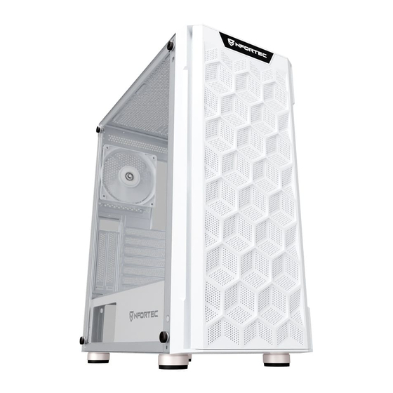
TECHNICAL SPECIFICATIONS ESPECIFICACIONES TÉCNICAS MODEL AZIR MODELO AZIR DIMENSIONS (L x W x H) 392mm x 210mm x 477mm DIMENSIONES (L x An x Al) 392mm x 210mm x 477mm WEIGHT 5,5Kg PESO 5,5Kg MATERIAL Steel 0,6mm SPCC, tempered glass... - Page 3 PC CASE GENERAL DIAGRAM DIAGRAMA DE INFORMACIÓN GENERAL Magnetic Dust filter Front mesh panel HDD/SSD enclosure bays Filtro de polvo magnético Panel frontal mallado Bahías para discos duros HDD y SSD Side tempered glass 120mm RGB Fans Front panel I/O Cristal templado lateral Ventiladores RGB 120mm Panel frontal de E/S...
- Page 4 FRONT PANEL I/O AND MOTHERBOARD CONNECTORS PANEL FRONTAL DE E/S Y CONECTORES PARA PLACA BASE USB3.0 USB2.0 HD AUDIO Reset Power ACCESORY BAG ACCESORIOS PARA INSTALACION PSU screws Motherboard standoffs Motherboard Screws Tornillos para Fuente de alimentación Soportes para placa base Tornillos para placa base HDD bay Screws Cable ties...
-
Page 5: Basic Installation
BASIC INSTALLATION INSTALACIÓN BÁSICA Disassemble the side panel and the front panel. Desmontar los paneles laterales y el panel frontal. Install the power supply. Instalación de la fuente de alimentación. Install the motherboard. Instalación de la placa base. Install HDD/SSD. Instalación de discos duros HDD/SSD. - Page 6 Make sure the screw holes for PSU and the PC case are aligned before screwing. Asegúrate que los huecos para los tornillos de la fuente de alimentación se alinean de manera correcta con los de la torre antes de atornillar. Make sure that the motherboard aims at the copper cylinder and install the standoffs (No.2) before screwing in with the No.3 screws.
- Page 7 Take off the hard disk enclosure for both HDD and SSD and install it with No.3/4 screws Desmonta el soporte para los discos HDD y SSD e instálalos con los tornillos No.3/4 Remove the bafle marked in the picture, make sure the VGA card aims at the motherboard slot and then fix VGA card and case with No.1 screw.
- Page 8 FRONT FRONTAL Fans → 3x 120mm Ventiladores → 3x 120mm → 2x 140mm → 2x 140mm Radiator up to 240mm Radiador hasta 240mm SUPERIOR Fans → 2x 120mm Ventiladores → 2x 120mm → 2x 140mm → 2x 140mm Radiator up to 240mm Radiador hasta 240mm REAR TRASERO...
- Page 9 A Z I R...
Need help?
Do you have a question about the AZIR and is the answer not in the manual?
Questions and answers