
Related Manuals for Instron SI Series


Summary of Contents for Instron SI Series
- Page 1 DUTCHESS COMMUNITY COLLEGE Materials Testing Lab RFB-DCC-08-2016 Appendix A Appendix A and Drawings...
- Page 2 APPENDIX A Industrial Products Group SI-Series Impact Testing Machine CLOUDED SECTIONS INDICATE INFORMATION RELATED TO CONTRACTOR RESPONSIBILTY Pre-Installation Manual M47-16824-EN Revision A www.instron.com The difference is measurable ®...
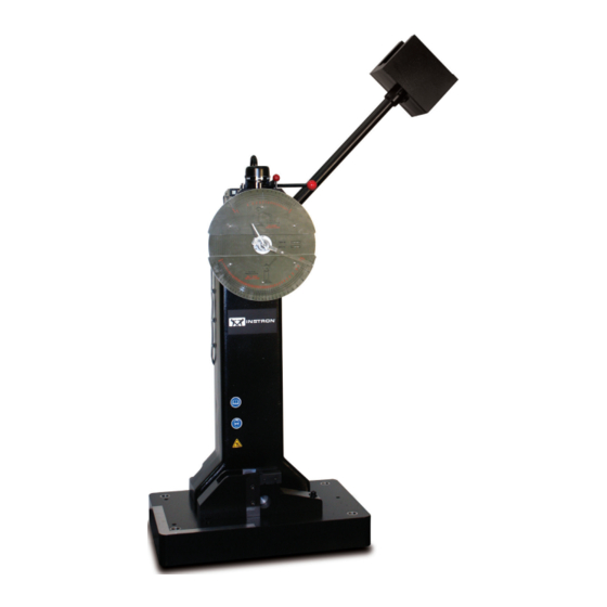
- Page 3 6. Pusher Arm 15. Tensile Anvil or Charpy Support Pendulum Shaft 16. Clamping Screw (Izod Vise) 8. Pendulum Head 17. Wooden Safety Block 9. Upper Dial 18. Shrouds Figure 1. Impact testing system components - non-motorized models. Product Support: www.instron.com...
-
Page 4: Customer's Responsibilities
“Pre-Installation (Shipment Arrival)”. Always verify your machine’s specific model when referencing any information in this manual; refer to the Instron sales order or quote (see customer copies), or the serial number tag located on the machine frame. Handling and transporting Unless specifically arranged otherwise, it is the customer’s responsibility to arrange the off-loading,... - Page 5 Instron does not dispute, the Ex-Works shipping terms apply. Under these terms, Instron is responsible for insurance cover while the testing system is in the factory up until it reaches the loading dock for shipping.
- Page 6 APPENDIX A Chapter 2: Specifications System physical dimensions Table 5. Dimensions of standard Impact machine frames. Machine Model Overall Height Overall Area (W x D) Net Weight 1820 mm 710 x 485 mm 450 kgs SI-1C3, SI-1K3 71.5 in 28 x 19 in 985 lbs 1.
-
Page 7: Site Preparation
24. ‰ Ensure that the environmental conditions of the installation site are appropriate for the system. See “Environmental conditions” on page 24. * Instron is not responsible for foundation recommendations. This should be reviewed with a certified civil engineer. - Page 8 4. Wall A. Pendulum Swing Area - 930 mm (36.5 in) radius B. Swing Clearance - Operator 915 mm (36 in) Work Space Drawing not to scale. Figure 2. Overhead view of machine safety zone of non-motorized models. Product Support: www.instron.com...
- Page 9 Recommended Tie Down Bolt Length 380 mm (15 in) Recommended Tie Down Bolt Extension Above Floor 150 mm (6 in) (Dimension B of Figure Instron Tie Down Bolt, T-bolts, 4 supplied when purchased • Part Number W-3573 • Bolt Length (Dimension A of Figure 467 mm (18.375 in)
- Page 10 (shield, J-bolt, etc.) must have a minimum pull-out load equal to the tensile strength of the mounting bolt used. The minimum bolt size recommended is 0.875 in diameter. Consult a foundation expert or civil engineer for further foundation recommendations. Product Support: www.instron.com...
- Page 11 It is also suggested that network drops, or digital phone lines, be within the general testing area. Instron’s goal is to provide remote diagnostics in order to resolve system issues. Having a network drop or digital phone line available will enable an Instron service representative to dial into the testing system’s...
- Page 12 ‰ Complete system preparations. See “System preparation” on page 30. ‰ Prepare for visit from the Instron service engineer to complete installation. See “Preparing for service visit” on page 30. Receiving The machine should arrive at the customer’s site in a single crate. A packing list is attached to the crate and is enclosed in an adhesive backed package labeled “Packing List Enclosed”.
-
Page 13: Moving The Machine
• Notify Instron and the common carrier immediately if there are any discrepancies. Moving the machine Before you begin Before moving the machine ensure that: •... -
Page 14: Equipment Required
4. Ensure the three 6 mm (0.25 in) thick steel plates are in the appropriate position for leveling the machine base (see “Foundation” on page 22). 5. Place the machine base on the foundation over the steel plates. 6. Level the machine, see “Leveling the machine” on page 28. Product Support: www.instron.com... -
Page 15: Leveling The Machine
4. When the grout has set, loosen the leveling screws, and then tighten the foundation bolts in a criss- cross pattern in small steps (68 N-m (50 ft-lbs)) until the appropriate torque is reached for your grade of bolt; for bolts purchased from Instron, see Table 8 on page 22. - Page 16 ITW Polymers Coatings North America ITWPRC 100 Non-Shrinking Cement Grout A.C. Horn Company Horn Non-Corrosive Grout Anti Hydro Company Axpandcrete R.M. Master Builders Embeco 636 or Master Flow 713 L & M Construction Chemicals Crystex Grout Sonneborn Building Products Sonogrout Product Support: www.instron.com...
-
Page 17: System Preparation
3. Place guard system around the post-impact pendulum swing area with the open end facing the machine frame. Preparing for service visit Prior to the arrival of the Instron service engineer, check that the following items have been completed: • The machine is on the proper foundation, grouted, leveled, and bolts tightened to appropriate torque. -
Page 18: Installation
Installation by Instron ........ - Page 19 For the heavy pendulum, insert the lower pin first and tap it firmly into place. Then rotate the pendulum/sheave up to shoulder height so that the upper pin hole is exposed. Insert the upper pin and tap it firmly into place. BY INSTRON - FOR INFORMATION ONLY M47-16824-EN...
- Page 20 3. Striker Socket Head Cap Screws 4. Tapered Pin Holes 5. Sheave 6. Pin Holes for Heavy Pendulum Pin Holes for Light Pendulum Front view of pendulum Figure 5. Pendulum and sheave orientation for non-motorized models. BY INSTRON - FOR INFORMATION ONLY Product Support: www.instron.com...
- Page 21 Accessories Installation of accessories such as tension-impact adapters, anvil insert for wide or round specimens, etc. that were purchased with your testing system are covered in the SI-Series Impact Testing System Operating Instructions. BY INSTRON - FOR INFORMATION ONLY M47-16824-EN...
- Page 22 APPENDIX A 5980 Series Dual Column Floor Frames CLOUDED SECTIONS INDICATE INFORMATION RELATED TO CONTRACTOR RESPONSIBILTY System Support M10-16250-EN Revision + The difference is measurable ®...
- Page 23 APPENDIX A Chapter: Introduction System Description and Terminology Figure 1-1 on page shows the location of components on 5982, 5984 and 5985 load frames. The 5988 and 5989 frames are substantially the same, except for the location of the power input and ground stud, as shown in Figure 1-2 on page 1-3.
-
Page 24: Chapter 2 Requirements And Specifications
APPENDIX A Chapter 2 Requirements and Specifications • Responsibilities........... . . 2-1 •... - Page 25 Upon special arrangements, an Instron service engineer can supervise the off-loading and transportation of the load frame to its final site. Contact Instron’s Professional Services department or your local Instron office for additional information on this service (refer to “Product Support”...
-
Page 26: Site Requirements
The customer must not make any attempt to install the load frame without an Instron service representative present. Initial Operation Once the installation is complete, Instron performs an initial operation of the load frame and a calibration check to ensure that it is working properly. -
Page 27: Floor Loading
Instron systems require “clean” and stable electrical power. Unless other arrangements are made with Instron, you are responsible for providing clean electrical power. An in-line power surge protector is recommended for all installations. If you purchased an environmental chamber with your system, it requires a dedicated electrical power supply that is separate from the power supply for the rest of the system. - Page 28 Ensure that a telephone line is located within the general testing area. This enables the user to contact Instron’s service department directly from the testing area so the user can perform the instructions provided and resolve the situation while on the telephone with the service representative.
- Page 29 APPENDIX A 5982, 5984 and 5985 Dimensions 50 ±16 Optional Base Extension Figure 2-2. 5982, 5984 and 5985 Load Frame Dimensions Product Support: www.instron.com 2-11...
- Page 30 APPENDIX A Chapter: Requirements and Specifications Table 2-5. 5982 with Single Test Space Frame Option Standard Extra Height Height and and Extra Width Extra Height Extra Wide Wide Dimension - mm (in) Letter Top plate length 1105 (43.5) 1105 (43.5) 1464 (57.6) 1464 (57.6) Horizontal test space...
- Page 31 Figure 2-3. Second Test Space Configuration Figure 2-4 on page 2-14 shows the dimensions for the second test space. Refer to Table 2- on page 2-14 Table 2-8 on page 2-14 to match the letter designations. Product Support: www.instron.com 2-13...
- Page 32 APPENDIX A Chapter: Requirements and Specifications 1037 Figure 2-4. Second Test Space Dimensions Table 2-7. 5982 with Second Test Space Frame Option Standard Height and Dimension - mm (in) Letter Width Extra Height Top plate thickness 148 (5.8) 148 (5.8) Overall height 2354 (92.7) 2905 (114.4)
- Page 33 APPENDIX A Chapter: Requirements and Specifications Base Beam Ø100 M10 x 25 Deep M16 x 30 Deep (10X) (8X or 12X for extra wide) M30 x 2-6H Ø40 x 3 Deep 40 Deep, LH Front of frame Figure 2-6. 5982 Base Beam Mounting Dimensions Ø100 M10 x 25 Deep M16 x 30 Deep...
- Page 34 Ø60 x 3 Deep Front of frame Topside of moving crosshead Ø60 x 3 Deep M10 x 25 Deep (10X) Ø51 Thru Ø100 Underside of moving crosshead Figure 2-10. 5984 and 5985 Moving Crosshead Mounting Dimensions Product Support: www.instron.com 2-21...
-
Page 35: Site Location
“Product Support” on page 1-10). Not all computers are compatible with Instron testing systems. If you intend to purchase a computer from an outside vendor, contact Instron Service to verify its compatibility. Additional charges may result from service that is required to evaluate or reconfigure non- approved computers. - Page 36 When the testing site is ready, and the frame has been moved to its final operating location, contact Instron Professional Services to schedule an installation appointment: Worldwide Contact your local Instron Sales and Service office. A list of Instron offices is available on our website at www.instron.com. In the United States 1-800-473-7838 &...
-
Page 37: Lifting And Handling
General Handling Precautions Only individuals experienced with the operation of lifting equipment and rigging techniques should attempt to lift or move an Instron system. Equipment operators must have the appropriate licenses and have complied with your local safety standards (e.g. the appropriate training required by OSHA in the U.S.). -
Page 38: Packaging Dimensions
Doing so may topple the load frame and cause personal injury and damage. Packaging Dimensions Instron recommends leaving the load frame in its packaging while moving it to its final site location within your building. Use the information in this section to verify that: •... - Page 39 • Do not open any of the packing boxes until the Instron service engineer arrives to install your testing system. The packing list indicates the total number of boxes that are included in the shipment.
-
Page 40: Using A Crane
APPENDIX A Righting the Frame from a Prone Position Using a Crane If you elect to use a crane to move the load frame, Instron recommends using professional riggers experienced in moving heavy equipment. Before You Begin Before moving the load frame ensure that: •... -
Page 41: Using A Forklift
6. Remove the slings from the crosshead. The frame can now be positioned into its operating location and then installed by an Instron service representative. To position the frame into its operating location, use the crosshead method to lift the frame. - Page 42 Ratchet lever hoist (come-along) to stabilize the base of the frame while moving the frame into an upright position. Procedure Prior to moving the frame, it is recommended that you contact Instron service for additional guidance when righting the frame. To lift the load frame into a vertical position: 1.
- Page 43 APPENDIX A Chapter: Lifting and Handling Crosshead Load frame base Shipping bolt (Total of 4) Forklift arm Shipping skid Figure 3-2. Lifting the Frame from the Base To transport the load frame using the frame base method: 1. Ensure that the frame is bolted to the shipping skid. 2.
- Page 44 When the frame is in the testing location, you can proceed with the installation process. Crane Method Instron recommends using professional riggers experienced in moving heavy equipment. To transport the load frame using the crane method: 1. Attach the two lifting slings to the crosshead and secure them to the crane hook as...
-
Page 45: Chapter 4 Installation
APPENDIX A Chapter 4 Installation • Level the Load Frame..........4-1 •... - Page 46 APPENDIX A Chapter: Installation Warning As you make adjustments, make sure no more than 12mm (0.5in) of thread is exposed. If you expose more thread, there is a risk that the threaded adapter can separate from the foot. 4. Rotate the spirit level 90° to verify that the load frame is level side to side and front to back.
-
Page 47: Power Supply Compatibility
There are dangerous voltages and rotating machinery inside the machine that may cause bodily injury or damage to equipment. The voltage settings are inside the machine and can only be changed by a qualified Instron Service Engineer. Contact Instron Professional Services for assistance if you need to change the voltage setting. - Page 48 APPENDIX A Chapter: Installation • To accommodate high in-rush currents, connect a time delay circuit breaker between the facility power source and the load frame (refer to Table 2-3 on page 2-8). The connector on the power cable must be compatible with the power source. If the power cable supplied with your system does not fit your power source outlet, add a male plug to the cable that is compatible with the voltage.
Need help?
Do you have a question about the SI Series and is the answer not in the manual?
Questions and answers