
Related Manuals for Instron 2716-010


Summary of Contents for Instron 2716-010
- Page 1 5kN, 30kN and 50kN Wedge Grips Reference Manual - Equipment M10-14052-EN Revision C The difference is measurable ®...
- Page 2 Instron is a registered trademark of Illinois Tool Works Inc. (ITW). Other names, logos, icons and marks identifying Instron products and services referenced herein are trademarks of ITW and may not be used without the prior written permission of ITW.
- Page 3 Caution is used where a hazard may lead to damage to equipment or to loss of data. Instron products, to the best of its knowledge, comply with various national and international safety standards, in as much as they apply to materials and structural testing.
- Page 4 Preliminary Pages Warnings Hazard - Press the Emergency Stop button whenever you consider that an unsafe condition exists. The Emergency Stop button removes hydraulic power or electrical drive from the testing system and brings the hazardous elements of the system to a stop as quickly as possible.
- Page 5 During system operation, keep away from the operating envelope of the robot. De-activate the robot before entering the envelope for any purpose, such as reloading the specimen magazine. Product Support: www.instron.com...
- Page 6 Preliminary Pages Warnings Hazard - Set the appropriate limits before performing loop tuning or running waveforms or tests. Operational limits are included within your testing system to suspend motion or shut off the system when upper and/or lower bounds of actuator or crosshead travel, or force or strain, are reached during testing.
- Page 7 Apply the specified torque to all load string fasteners and the correct setting to wedge washers or spiral washers. Visually inspect highly stressed components such as grips and threaded adapters prior to every fatigue test for signs of wear or fatigue damage. Product Support: www.instron.com...
- Page 8 Preliminary Pages M10-14052-EN...
-
Page 9: Table Of Contents
Checklist ............. Product Support: www.instron.com... - Page 10 Preliminary Pages Procedure ............Chapter 4: Operation .
-
Page 11: Chapter 1: Introduction
This manual describes the 5 kN wedge action grips, two versions of the 30 kN wedge action grips, and the 50 kN wedge action grips. These are: • Catalog number 2716-010 - 5 kN wedge action grips • Catalog number 2716-015 - 30 kN wedge action grips •... -
Page 12: Purpose
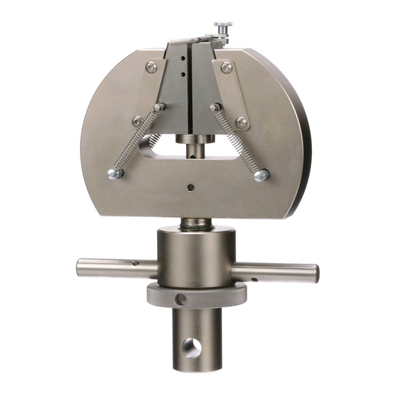
Figure 1 shows the 2716-015 (30 kN) version of the grips. The 2716-010 (5 kN) version looks exactly the same. The high temperature version (2736-015) is similar except that there are four handles on each grip to facilitate tightening the grips in the confined space of a temperature chamber. - Page 13 A compressive test load eliminates any gripping force and causes the specimen to slip from the grips. The open front design of the grips lets you change jaw faces to accommodate flat, round or different size specimens. Product Support: www.instron.com...
-
Page 14: Description
Chapter: Introduction Description Figure 2. Grip Components (2716-015) M10-14052-EN... -
Page 15: Components
Specimen Centering Device The optional specimen centering device is a small metal block which two screws attach to the outside of a jaw face. A knurled thumb screw secures a thin L-shaped arm which extends outward across the face. Product Support: www.instron.com... -
Page 16: Functional
Chapter: Introduction Functional Figure 3 illustrates the grip in the closed and open positions. Figure 3. Grips in the Closed and Open Positions Closed Adjust the specimen centering device before you place a test specimen between the open jaw faces. When you turn the handles to close the grip on a specimen, the screw action of the control nut and body threads move the body away from the test specimen and push the bearing plate against the jaw faces. - Page 17 When you turn the control handles to open the grip, the screw action of the control nut and body threads move the body toward the test specimen. The movement eliminates the gripping force on the specimen and allows the four springs to retract the jaw faces away from the specimen. Product Support: www.instron.com...
- Page 18 Chapter: Introduction M10-14052-EN...
-
Page 19: Chapter 2: Specifications
Jaw Faces ............21 Dimensions Figure 4 illustrates the grip dimensions. Product Support: www.instron.com... - Page 20 Chapter: Specifications Figure 4. Dimensions Table 1. Dimensions 2716-010 2716-015 & 2736- 2716-020 (5 kN) 015 (30 kN) (50 kN) Designation Measurement Value mm (in) Value mm (in) Value mm (in) Effective length 191 (7.50) 203 (8.00) 208.5 (8.22) Body width 144 (5.67)
-
Page 21: Grips
Grips Grips Table 2. Grip Specifications 2716-010 2716-015 & 2736-015 2716-020 Parameter (5 kN) (30 kN) (50 kN) Load Capacity 5 kN 30 kN 50 kN 510 kgf 3060 kgf 5100 kgf 1125 lbf 6744 lbf 11240 lbf Test Application... - Page 22 Chapter: Specifications Table 3. Jaw Face Specifications Specimen Catalog Specimen Thickness Number Type mm (in) Surface 2703-151 Flat 0 to 6.4 1.5mm pitch (16 teeth per in.) (0 to 0.25) 2703-152 Flat 6.4 to 12.6 1.5mm pitch (16 teeth per in.) (0.25 to 0.50) 2703-155 Flat...
- Page 23 Rockwell C. The serrations may not penetrate extremely hard specimens; also, hard specimens will cause excessive serration wear. The following are common jaw face specifications: Parameter Specification Construction Tool steel Height 57 mm (2.2 in.) Width 25 mm (1 in.) Product Support: www.instron.com...
- Page 24 Chapter: Specifications M10-14052-EN...
-
Page 25: Installation
A clevis pin coupling is typically used for attaching the grips to an electromechanical test system. Figure 5 on page illustrates the clevis pin coupling. A male shank connects to a female clevis socket, which connects to either the load cell or to the baseplate. A Product Support: www.instron.com... - Page 26 Chapter: Installation clevis pin couples the shank and socket together. A locknut assures that no end play exists in the grip to load frame connection. Figure 5. Clevis Pin Couplings M10-14052-EN...
-
Page 27: Installing The Jaw Faces
You eliminate any end play by tightening a locknut against the actuator piston rod or load cell and the grip locknut against the grip adapter. Figure 6. Threaded Coupling Installing the Jaw Faces Equipment You need a dispenser of Molykite g-N paste. Product Support: www.instron.com... -
Page 28: Checklist
Chapter: Installation Checklist Before you install the faces, check for the following: • The grips are in the open position. • The jaw faces are the correct size for the test specimen. • There are no jaw faces or specimen in the grips. Procedure Warning Hazard - Do not perform any testing if the side plates are not in place. -
Page 29: Installing The Spacers And Side Plates
The grips can be used either with the spacer for thinner specimens, or without the spacer for thicker specimens.Table 4 on page summarizes the ranges of specimen thickness available with and without the spacer. Product Support: www.instron.com... -
Page 30: Equipment
Chapter: Installation The spacers replace the side plates when testing thinner specimens. Both the spacers and side plates perform an important safety function preventing the jaw faces from moving side to side. You must have either the spacers or the side plates in place before testing begins. - Page 31 Step 4. Repeat Step 1 through Step 3 for the remaining three side plates. 5. Proceed with installing the jaw faces. Refer to “Installing the Jaw Faces” page 27. Figure 8. Spacer in Detail Product Support: www.instron.com...
-
Page 32: Preloading The Load String
Chapter: Installation Figure 9. Installing Side Plate and Spacer Preloading the Load String All load string components must be rigid and not allow any backlash which could degrade the integrity of the test results. You must preload the load string attachment kits to eliminate backlash. -
Page 33: Checklist
Removing Preload • spanner wrench (1/4 in.) - Instron part #80-4-4 Checklist Check for the following conditions before you preload the grips: • The jaw faces are installed. • The side plates are secure. If you are using a 50 kN wedge grip, ensure that either the spacers or side plates are fitted on the grip and are secure. -
Page 34: Equipment
Chapter: Installation Equipment You need the following items: • a specimen capable of withstanding a tensile load equal to the current load string preload • spanner wrench (1/4 in.) Checklist Check for the following conditions before you preload the grips: •... -
Page 35: Operation
The size and type of jaw faces are appropriate for the test specimen. • The side plates are secure. If you are using a 50 kN wedge grip, ensure that either the spacers or side plates are fitted on the grip and are secure. Product Support: www.instron.com... -
Page 36: Procedure
Chapter: Operation • If using 50 kN grips, either the side plates or spacers are installed, whichever is appropriate for the thickness of the test specimen. • There is enough space between the upper and lower grip to install the specimen. •... -
Page 37: Removing A Specimen
Check for the following conditions before you remove a specimen: • The test system is not exerting a load on the specimen. • There is no measuring device, such as an extensometer or LVDT, on the specimen. Product Support: www.instron.com... -
Page 38: Procedure
Chapter: Operation Procedure 1. Turn the upper grip control nut, according to the grip label icon, until the jaw faces no longer engage the specimen. Caution Secure fragile specimens by some means before you open the lower grip. 2. Turn the lower grip control nut, according to the grip label icon, until the jaw faces no longer engage the specimen. -
Page 39: Chapter 5: Maintenance
• Lubricate the attachment kits with a light oil to prevent corrosion. Do not lubricate the gripping area of the jaw faces. Oil or grease decreases the effec- tive gripping force and clogs the jaw face serrations. Product Support: www.instron.com... -
Page 40: Troubleshooting
Chapter: Maintenance Troubleshooting Improper adjustments or a lack of maintenance is the cause of most grip operating problems. To help you when a problem develops, Table 5 suggests a probable cause and recommends a solution. Table 5. Troubleshooting Problem Cause Remedy Specimen slips while under Wrong size or type of jaw face... -
Page 41: Illustrated Parts
Temperature) version is that there are four handles on the high temperature version. The 2716-015 (30 kN) wedge grip is visually similar to both the 2716-010 (5 kN) and 2716-020 (50 kN) wedge grips, so the same graphic is used to identify parts for all three grips. -
Page 42: Ancillary Parts
Chapter: Illustrated Parts Ancillary Parts The Ancillary Parts list contains additional items for installing and maintaining the grips. There is a description and Instron part number for each item. M10-14052-EN... -
Page 43: Parts Lists
Parts Lists Parts Lists Figure 11. Illustrated Parts Product Support: www.instron.com... - Page 44 Chapter: Illustrated Parts Table 6. 2716-010 (5 kN) Wedge Grip - Parts List Item Description Part Number Quantity Screw M4 x 8 201S87 Bearing Pad T566-5 Body T566-4 Control Nut T566-2 Spindle T566-1 Pin, 10 x 35 54-53-1054 Check Nut...
- Page 45 Pin, 5/32 x 1 in. 26-6-2 Spring Extension 66-1-1069 Side Plate T566-6 Screw M4 x 8 204F123 Specimen Centering Device 2716-011 Including: Bracket T566-14 Thumbscrew 71-2-55 Stop T566-115 Screws 201T98 Faces Refer to 2 pair Table 3 on page Product Support: www.instron.com...
- Page 46 Chapter: Illustrated Parts Table 8. 2736-015 (30 kN) High Temp. Wedge Grip - Parts List Item Description Part Number Quantity Screw M4 x 8 201S87 Bearing Pad T566-5 Body T566-54 Control Nut T566-51 Spindle T566-52 Pin, 10 x 35 54-53-1056 Check Nut T2-309 Handle...
- Page 47 Pin, 5/32 x 1 in. 54-5-10 Spring Extension 66-1-1069 Side Plate T566-6 Spacer T566-135 Screw M4 x 8 204F123 Specimen Centering Device 2716-011 Including: Bracket T566-14 Thumbscrew 71-2-55 Stop T566-115 Screws 201T98 Faces Refer to 2 pair Table 3 on page Product Support: www.instron.com...
-
Page 48: Ancillary Parts
Chapter: Illustrated Parts Ancillary Parts Table 10. Ancillary Parts List Description Part No. Spanner Wrench 80-4-4 Molykote g-N Paste 105-1-28 M10-14052-EN... -
Page 49: Index
Troubleshooting ....40 Dimensions ......19 Product Support: www.instron.com... - Page 50 Parts list ......43 30 kN ambient temperature grips ..45 30 kN high temperature grips .
- Page 52 Product Support: www.instron.com...
Need help?
Do you have a question about the 2716-010 and is the answer not in the manual?
Questions and answers