
Related Manuals for Huayuan Electric NB-500HK


Summary of Contents for Huayuan Electric NB-500HK
- Page 1 NB-500HK MIG/MAG/CO WELDING MACHINE MANUAL INSTRUCTION (PLEASE READ CAREFELLY BEFORE OPERATION)
- Page 2 Safety Depends on You Huayuan arc welding and cutting equipment are designed and built with safety in mind. However, your overall safety can be increased by proper installation. DO NOT INSTALL, OPERATE OR REPAIR THIS EQUIPMENT WITHOUT READING THIS MANUAL AND THE SAFETY PRECAUTIONS CONTAINED THROUGHOUT.
- Page 3 Ca u t i o n s Arc and arc rays may harm health. Arc welding can be hazardous. All performing welding workers ought to have health qualification that provided by authority organization. Protect yourself and others from possible serious injury or death. Keep children away. Pacemaker wearers should consult with their doctor before operating.
- Page 4 welding current is strong enough to damage them while having short circuit with them. Cylinder may explode if damaged. Make sure that the gas in the storage cylinder is qualified for welding, and the decompression flow-meter, the adapter and the pipe are all in good condition. Always keep cylinders in an upright position securely chained to an undercarriage or fixed support.
-
Page 5: Table Of Contents
CONTENT 1, Summary................................ 1 1.1 Model instruction..........................1 1.2 Main features............................1 1.3 Usage..............................1 1.4 Working condition and environment....................1 1.5 Symbol instruction..........................2 2, Technical Specifications..........................2 2.1 Main technical parameters........................2 3, Panel and function............................3 3.1 Front panel function..........................3 3.2 Down front panel.......................... - Page 6 8.1 Maintenance............................19 8.2 Repairing............................19 9, Common faults and eliminating methods....................20 10, Packing List..............................21 11, Annex................................22 11.1 NB-500HK electrical schematic diagram..................22...
-
Page 7: 1, Summary
1, Summary 1.1 Model instruction B — □□□ HK Product Classification Code Rated welding current Semi-automatic welding Mig/Mag/CO2 welding machine 1.2 Main features ● Panel simple, easier parameters set and operation. ● Arc characteristic function is adjustable, suitable different welding condition. ●... -
Page 8: Symbol Instruction
Negative Current Voltage MIG/MAG Table 1 Symbol instruction 2, Technical Specifications 2.1 Main technical parameters Model Item Unit NB-500HK Input power V/Hz 3~380±15% 50/60 Rated input capacity Rated input current Rated output current Rated output voltage Rated open circuit voltage Rated duty cycle 100%(40℃)... -
Page 9: 3, Panel And Function
Crater current 60~500 Crater voltage 16~39 Suitable wire diameter φ1.0、φ1.2、φ1.6 Cooling mode 风冷 F 级 Insulation grade IP21S Ingress protection Dimension(L*W*H) 640×290×580 Net weight 38kg Table 2 Main technical parameter 3, Panel and function 3.1 Front panel function Up panel function as follows figure.1 ⑸... -
Page 10: Down Front Panel
will light, and the welder will turn off the output; If the air inlet or outlet or the air duct is blocked, the fan rotates abnormally, the ambient temperature is too high, and the welding machine is overloaded and used continuously, etc., the internal temperature will be too high;... -
Page 11: Rear Panel Instruction
⑴ ⑵ ⑶ Fig.2 Front panel function (1) Control cable socket: Used to connect the wire feeder control cable. (2) Welder output positive pole: used to connect the wire feeder welding cable. (3) Welder output negative: used to connect the work-piece connection cable. 3.3 Rear panel instruction Rear panel instruction as follow Fig.3:... - Page 12 ⑴ ⑵ ⑶ ⑸ ⑷ Fig.3 Rear panel function (1) Power over-current protection switch: When the welder has abnormal input over-current, disconnect the power supply to protect it. This switch is for protection only. Please install a power switch when the welder is installed. (2) Heater power connector: The power socket of the gas heater, the output voltage is AC36V/1.2A.
-
Page 13: 4, Installation
4, Installation 4.1 Power supply requirement (1)Power supply: 3~50/60Hz 380VAC. (2)Grid voltage fluctuation range: <±15%. (3)Frequency fluctuation range: <±1%. (4)Three-phase voltage imbalance rate:<±5%. (5) When using the engine generator: The generator output power is required to be more than twice the rated input power of the welding power source, and the compensation coil is provided. - Page 14 Fig.4 Welder installation...
-
Page 15: Welder And Wire Feeder Connection
4.3 Welder and wire feeder connection Please refer to fig.4 to connect: (1) Connect one end of the negative output cable to the “-” output terminal block of the welder and the other end to the work-piece. (2) Connect one end of the positive output cable to the “+” output terminal block of the welder and the other end to the wire feeder connector. -
Page 16: 2) Checking After Connection
Figure 5 ● Wear fur gloves and safety shoes to protect the skin and bare parts; ● Wear a shield filter glass that match with different welding current to protect eyes; ● There should be ventilation in the welding place to prevent breathing in deleterious gas. -
Page 17: 3) Switch Operation And Gas Flow Adjustment
(3) Switch operation and gas flow adjustment Step 1: Turn on the power switch of distribution box; Step 2: Press “weld/check gas” knob to check gas position. Step 3: After unscrewing the gas cylinder switch, slowly unscrew and adjust the flow adjustment knob switch of the gas flow meter so that the indication value on the flow-meter is the welding required value.(Refer to table 6.) Step 4: Press “weld/check gas”... - Page 18 wire feeding wheel slot, and then the guiding nozzle is inserted; Step 5: pressing the pressing arm to press the welding wire, then lifting the handle to press the pressing arm, and rotating the handle to a moderate pressure; Step 6: Check the welding nozzle of the welding torch. The hole diameter should be the same as the diameter of the wire used.
-
Page 19: Welding Operation
5.2 Welding operation (1) 4-Step weld operation(Non initial) ● Suitable for welding long seam or medium thick plates ● The filling of the arc pit at the end of the welding can be achieved by welding with the arc; ● During the welding process, when the continuous arc breaking occurs for more than 0.5 seconds, the self-locking is automatically released and the welding is completed. -
Page 20: 2) 2-Step Weld Operation (Non Initial And Crater)
current (or adjusted to the required value in advance, generally adjusted to 60 to 70% of the normal welding current), so that the depression at the end of the welding can be filled. When the welding torch switch is released again, the wire is immediately braked to stop, and the ignition state is reduced to the burn-in voltage. - Page 21 Angle Thick Wire Weld Weld elonga weld Weld current Gas flow Item ness diameter voltage speed tion length (L/ min) (mm) (mm) (cm/min) (mm) (mm) 3~3.5 1.0、1.2 100~110 18~19.5 50~60 10~15 3~3.5 1.0、1.2 115~125 19.5~20 50~60 10~15 3~3.5 1.0、1.2 130~140 19.5~21 50~60 10~15...
- Page 22 Angle Thick Wire Weld Weld elonga weld Weld current Gas flow Item ness diameter voltage speed tion length (L/ min) (mm) (mm) (cm/min) (mm) (mm) 10~ 1.0、1.2 150~180 20~22 35~45 10~15 10~ 200~250 24~26 40~50 10~15 High 2.3~ Speed 65~75 16~17 40~45 10~15...
- Page 23 Table 7 Ι type butt welding Thickne Wire Weld Weld Weld elongation( Gas flow Item dia. current voltage speed G(mm) mm) (L/min) (cm/min) (mm) (mm) (A) (V) 60~70 16~16.5 50~60 75~85 17~17.5 50~60 10~15 80~90 17~18 50~60 10~15 95~105 18~19 45~50 10~15 1、1.2...
-
Page 24: 7, Working Principle
7, Working principle 7.1 Working principle NB-500HK gas shield welding machine adopts the latest electron device----IGBT is the key inverter device. The three phase AC power is transformer into 20KHz high frequency voltage after bridge rectified. The high frequency voltage output welding voltage after transforming, rectifying and filtering. -
Page 25: Component List
7.3 Component list Component name Component model Code Remarks Air breaker DZ47-63/3P D63 3 phase Bridge MDS100-12 rectifier IGBT module 2MBI100VA-120-50 V2、V3 Diode module MMF200ZB040DK1 V4、V5、V6 Hall sensor TKC500BR Control TN06 transformer Cooling motor 200FZY6-SF/AC220 Control board PN14 Table 8 Component list 8, Maintenance and repairing Note: When maintain or repair, the power must be cut off. -
Page 26: 9, Common Faults And Eliminating Methods
9, Common faults and eliminating methods If there some problems that can not be judged or solved, please do not hesitate to contact our company to get some technical assistance. Please do not repair or open the machine arbitrarily. There is high voltage after cutting power for 10 minutes, only qualified electrician can operate! Common faults and eliminating methods: (see below sheet) Table 9 Common faults and eliminating methods... -
Page 27: 10, Packing List
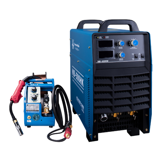
10.Clean the wire feeding pipe; 10.Too much dirt in wire feed pipe; 11.Fasten the ground wire; 11.Ground wire gets flexible; 10, Packing List 1. NB-500HK Power source 2.Wire feeder 3.Heater 4.Composite cable 5.Earth cable 6.Torch 7.Documents: operation manual, certificate, warranty... -
Page 28: 11, Annex
11, Annex 11.1 NB-500HK electrical schematic diagram... - Page 29 The final explanation rights reserved to Huayuan Company! If there is any change in the manual instruction, forgive not to inform separately! Chengdu Huayuan Electric equipment Co.,Ltd. Address: Wuhou National Science Park, Chengdu, China Postcode: 610045 Telephone:0086-28-85744098 Fax:0086-28-85744095 E-mail: hwayuansales@163.com...
Need help?
Do you have a question about the NB-500HK and is the answer not in the manual?
Questions and answers