Table of Contents
Advertisement
Quick Links
MODEL 9183
NetClock/GPS Master Clock
INSTRUCTION MANUAL
95 Methodist Hill Drive
Suite 500
Rochester, NY 14623
Phone: 585.321.5800
Fax: 585.321.5219
www.spectracomcorp.com
Revisions, if any, are located at the end of the manual.
Part number 9183-5000-0050
Manual Revision J
October 2006
Current to software version 2.3.0 (refer to 2.3.1 Addendum)
Advertisement
Chapters
Table of Contents
Troubleshooting

Related Manuals for Spectracom 9183

Summary of Contents for Spectracom 9183
- Page 1 95 Methodist Hill Drive Suite 500 Rochester, NY 14623 Phone: 585.321.5800 Fax: 585.321.5219 www.spectracomcorp.com Revisions, if any, are located at the end of the manual. Part number 9183-5000-0050 Manual Revision J October 2006 Current to software version 2.3.0 (refer to 2.3.1 Addendum)
- Page 2 Copyright © 2005 Spectracom Corporation. Contents of this publication may not be reproduced in any form without the written permission of Spectracom Corporation Printed in USA. Specifications subject to change or improvement without notice. Spectracom, NetClock, TimeView and Legally Traceable Time are Spectracom registered trademarks.
- Page 3 If in Spectracom’s judgment the defective condition in a Spectracom product is for a cause listed above for which Spectracom is not responsible, Spectracom will make the repairs or replacement of components and charge its then current price, which buyer agrees to pay.
-
Page 4: Table Of Contents
GENERAL INFORMATION ..................1-1 Introduction ....................... 1-1 Warranty Information and Product Support ............1-2 Unpacking ........................1-3 1.3.1 Package Contents ..................... 1-3 Model 9183 Specifications ..................1-4 1.4.1 Receiver ........................1-4 1.4.2 RS-232 Serial Setup Interface Port ................1-4 1.4.3 10/100 Ethernet Port .................... - Page 5 2.6.5 Connection Method....................2-11 2.6.6 Termination......................2-16 PRODUCT CONFIGURATION.................. 3-1 Network Configuration..................... 3-1 3.1.1 To configure the product to work on a network via the Serial Setup port....3-2 3.1.2 Initial network setup ....................3-3 3.1.3 Default and Recommended Configurations............. 3-6 Login...........................
- Page 6 Installing Certificates ..................... 3-84 3.14.8 Using Externally generated Certificates ..............3-85 3.14.9 What to do if you cannot get into a secure Spectracom Product ......3-86 Signature Control for the frequency output............3-88 SNMP ........................3-90 3.16.1 SNMP Configuration ..................... 3-90 3.16.2...
- Page 7 5.4.1 No GPS reception ....................5-4 5.4.2 Low GPS Quality..................... 5-5 Modem Dial-out (Option 3) troubleshooting ............5-6 5.5.1 Test 1: To verify modem is dialing and connecting to NIST in stand- alone mode:5-6 5.5.2 Test 2: To verify operation of the modem while connected to the NetClock..5-8 Customer Service ....................
- Page 8 net mac ........................7-18 net mask ........................7-19 net show........................7-20 net http ........................7-20 opt ..........................7-22 reboot [bootloader] ....................7-23 rem..........................7-24 sec..........................7-25 sec help ........................7-26 sec level........................7-27 sec password ......................7-28 ser..........................7-29 update ........................7-30 7.29.1 update app ......................
- Page 9 List of Figures Figure 2-1: Cabling recommendations..................2-5 Figure 2-2: Model 8226 Impulse Suppressor................2-6 Figure 2-3: Model 8227 Inline Amplifier ................... 2-6 Figure 2-4: Serial port connector ....................2-8 Figure 2-5: Remote Outputs......................2-9 Figure 2-6: RS-485 Output ....................... 2-10 Figure 2-7: One-Way Bus Installation..................
- Page 10 Figure 3-31: A new Certificate Request and Self Signed Certificate ........3-83 Figure 3-32: Installing a new Certificate .................. 3-84 Figure 3-33: Using External Certificate..................3-86 Figure 3-34: Signature Control configuration page ..............3-89 Figure 3-35: SNMPv1 Setup Screen..................3-90 Figure 3-36: System Time ......................
-
Page 11: General Information
Our NetClock is a direct response to customer needs for cutting-edge synchronization technology at an affordable price. The Model 9183 is called an NTP time server as it provides disciplined timing using NTP (Network Time Protocol), and is also called a Master Clock as it meets or exceeds the NENA (National Emergency Numbers Association) master clock standard. -
Page 12: Warranty Information And Product Support
Warranty Information and Product Support Warranty information is found on the leading pages of this manual. Spectracom continuously strives to improve its products and therefore greatly appreciates any and all customer feedback given. Technical support is available by telephone. Please direct any comments or questions regarding application, operation, or service to Spectracom Customer Service Department. -
Page 13: Unpacking
10-pin terminal block connector Jeweler’s type screwdriver (For tightening the screws on the terminal blocks) Terminating Resistors, 120 Spectracom models that have the modem dial-out feature (Option 3) enabled will also receive the following: Serial Modem kit Null modem adapter... -
Page 14: Model 9183 Specifications
Output jitter within +/-50 microseconds of UTC typical. Clients supported: The number of users supported depends on the class of network and the subnet mask for the network. A gateway greatly increases the number of users. Page 1-4 Model 9183 Instruction Manual... -
Page 15: Communication Port
±1 millisecond of UTC. Configuration: Baud rate and output Data Formats are selected using the web browser user interface. Bit rate selections are 1200, 2400, 4800, and 9600 baud. There are eight Data Format selections available. Model 9183 Instruction Manual Page 1-5... -
Page 16: Front Panel Display
AM Carrier: IRIG B-1000 Hz. IRIG E-100 Hz or 1000 Hz. AM Signal Level: Adjustable from 0 to 10 Vp-p mark amplitude into loads of 600 ohms or greater. Factory set to 2.0 V p-p. Page 1-6 Model 9183 Instruction Manual... -
Page 17: 1Pps Output
BNC female Signature Control: This configurable feature removes the output signal whenever a major alarm condition or loss of time sync condition is present. The output is restored when the fault condition is corrected. Model 9183 Instruction Manual Page 1-7... -
Page 18: Input Power
90 to 240 VAC, 47 to 63 Hz through an IEC 320 universal connector. North American AC power cord supplied. AC cables for other countries available locally. The Spectracom P/N for the power supply is PS06-0E0J-DT01 DC input: 9.5 to 30 VDC, 10 watts, through a CE/UL/CSA-approved power adapter (supplied). -
Page 19: Installation
(Refer to section 3.6.1). Note: Use of a window-mount antenna with a Model 9183 NetClock is not recommended if using an OCXO (Option 5) or Rubidium (Option 4) type oscillator in the NetClock. -
Page 20: Table 2-1: Time Zone Offsets Available For Data Outputs
UTC. It can’t be configured as local time. IRIG port on rear panel +/-12:00 None IRIG B IRIG port on rear panel +/-12:00 None IRIG E Table 2-1: Time Zone Offsets available for Data Outputs Page 2-2 Model 9183 Instruction Manual... -
Page 21: Required Tools And Cables
Note: Auto-Negotiate, which determines the network settings to use, only occurs at power-on. Always connect the Ethernet cable before powering-on the unit for the first time. If the Ethernet cable is connected after power-on, the unit will default to 10 Mbps and half duplex. Model 9183 Instruction Manual Page 2-3... -
Page 22: Gps Antenna Installation
Using Spectracom CAL7xxx or Times Microwave LMR-400 coax, the maximum antenna cable length permitted is 200 feet because the Model 9183 allows 12 dB of loss. An amplifier is needed whenever antenna cable lengths exceed 200 feet. Installations requiring longer antenna cables may use the Model 8227 Inline Amplifier, or lower loss cable. -
Page 23: Model 8224 Gps Splitter
The Model 8224 should be installed indoors. 2.4.4 Model 8226 Impulse Suppressor Spectracom recommends the use of an inline coaxial protector for all products with an outside antenna. Spectracom offers the Model 8226, Impulse Suppressor, to protect the receiver from damaging voltages occurring on the antenna coax. -
Page 24: Model 8227 Gps Inline Amplifier
2.4.5 Model 8227 GPS Inline Amplifier An inline amplifier is required whenever GPS antenna cable lengths cause greater than 12 dB attenuation. Using Spectracom CAL7xxx coax, an amplifier is needed whenever antenna cable lengths exceed 200 feet. The Model 8227 GPS Inline Amplifier, shown in Figure 2-2, extends the maximum cable length to 600 feet. -
Page 25: Ethernet Network Cabling
When connecting directly to a PC, use a crossover wired cable. 2.5.1 Optional CNC3000 cable kit: Spectracom offers an available cable kit called the CNC3000. This kit consists of three cables: 1) Six foot RS-232 Setup port cable DB9M to DB8F for initial configuration 1) Six foot Cat 5 crossover LAN cable for direct PC connection 1) Six foot Cat 5 patch LAN cable for LAN hub link. -
Page 26: Remote Port And Serial Comm Port Output Pin-Outs And Wiring
Serial RS-232 Comm ports. 2.6.1 Serial Comm ports The rear panel of the Model 9183 has two RS-232 SERIAL COMM ports that are available to synchronize peripheral devices. These ports can provide RS-232 output data to synchronize external devices that can accept RS-232 Data Formats as an input. The available Data Formats are listed in Section 6. -
Page 27: Remote Port
RS-485 characteristics make it ideal to distribute time data throughout a facility. Each Remote Output can provide time to 32 devices at cable lengths up to 4,000 feet. Refer to Figure 2-6 for a schematic representation of each RS-485 output driver. Relative to RS-485 specifications, the A Model 9183 Instruction Manual Page 2-9... -
Page 28: Remote Output Usage
Error! Objects cannot be created from editing field codes. Figure 2-6: RS-485 Output Spectracom offers many devices that accept the RS-485 data stream as an input reference. These products include display clocks, RS-485 to RS-232 converters, Ethernet Time Servers, and radio link products to meet various time applications and requirements. -
Page 29: Connection Method
A branched or star configuration is not recommended. This method of connection appears as stubs to the RS-485 transmission line. Stub lengths affect the bus impedance and capacitive loading which could result in reflections and signal distortion. Model 9183 Instruction Manual Page 2-11... -
Page 30: Figure 2-8: Split Bus Configuration
Block Block In/Out Twisted RS-485 Pair Cable Time Data Bus RS-485 Terminal Terminal RS-485 Terminal In/Out Block Block Output Block 8179T TimeView 230 NetClock TimeTap Master Clock DISPLAY RS-232 Figure 2-8: Split Bus Configuration Page 2-12 Model 9183 Instruction Manual... -
Page 31: Figure 2-9: Wire Strain Relief
Most RS-485 connections found on Spectracom equipment are made using a removable terminal strip. A jaw that compresses the wires when tightened secures the wires. When using small diameter wire, 22-26 gauge, a strain relief can be fashioned by wrapping the stripped wire over the insulating jacket as shown in Figure 2-9. -
Page 32: Figure 2-10: Timeview Rs-485 Interface
RS-232 interface that receives operational power from the RS-232 flow control pins RTS or DTR. Connect the TimeTap to the RS-485 data bus as shown in Figure 2-11. Figure 2-11: Model 8179T TimeTap RS-485 Interface Page 2-14 Model 9183 Instruction Manual... -
Page 33: Figure 2-12: Model 9188 Rs-485 Interface
Spectracom Model 9188 is an Ethernet Time Server that supports NTP and SNTP time protocols. The Model 9188 accepts Format 0, Format 2 or Format 8 (Format 8 is not available on all Model 9188’s- contact Tech Support for additional information) and connects to the RS-485 data bus through a three-position terminal block. -
Page 34: Termination
Figure 2-8. In a split bus configuration, terminate the devices installed on each end of the bus. Most Spectracom products include a built-in termination switch to terminate the RS-485 bus when required or a resistor is supplied with the equipment if no termination switch is available. -
Page 35: Product Configuration
(For security reasons HTTP should be disabled when HTTPS is the desired connection method to the web browser user interface). This is a toggle option to enable or disable the unit's SSH interface SSH: Model 9183 Instruction Manual Page 3-1... -
Page 36: To Configure The Product To Work On A Network Via The Serial Setup Port
Figure 3-1: Serial Setup Interface port connector SIGNAL DESCRIPTION Receive Data (RS-232 output data to PC) Transmit Data (RS-232 input data from PC) Signal Common Data Set Ready Request to Send Clear to Send Serial Setup port pin-outs Table 3-1: Page 3-2 Model 9183 Instruction Manual... -
Page 37: Initial Network Setup
If the unit has not yet been configured for a network, it will boot with the default settings and the ‘Spectracom login:’ prompt will appear; Login as administrator to change the default settings. Note: To make changes to the settings, you must be logged in with configuration or administrator privileges. - Page 38 Choose "System Setup" from the bottom frame and "Network" from the left frame. All fields will display the current system settings. At the bottom of the frame, clicking Reset will revert any changes made at this window since last pressing Submit. Page 3-4 Model 9183 Instruction Manual...
- Page 39 NetClock will immediately start using the new IP address. This will cause the web browser user interface to stop responding. Move the NetClock to the network and you should then be able to re-access the web browser user interface with any networked PC by using the new IP address. Model 9183 Instruction Manual Page 3-5...
-
Page 40: Default And Recommended Configurations
Command Line Interface Enabled – Using customer-generated certificate and key or default HTTPS Web User Interface Spectracom self-signed certificate and common public/private key SSH/SCP/SFTP enabled with unit unique 1024 bit keys Disabled or Enabled with: – SNMP v3 w/ encryption* SNMP... -
Page 41: Login
Note: For security reasons, the Admin and Config mode login lasts for 15 minutes or until the NetClock is rebooted (Whichever occurs first). You will be exited out of the login after 15 minutes as the connections reset every 15 minutes. Model 9183 Instruction Manual Page 3-7... -
Page 42: Figure 3-2: Log-In Permissions
CAUTION: The Administrator login provides the most power to change settings but an erroneous entry could cause the NetClock to malfunction or not perform within specifications. Only technicians trained in NetClock operations should be given access to the Administrator mode. Page 3-8 Model 9183 Instruction Manual... -
Page 43: Figure 3-3: Configuration Mode Log-In
Type the password for the mode selected. Note that the password is capital-letter sensitive. Figure 3-3: Configuration mode Log-in Figure 3-4: Administrator mode Log-in No Password? That’s OK; you can still view the unit’s configuration settings in the read-only mode. Model 9183 Instruction Manual Page 3-9... -
Page 44: To Change The Default Login Password Values
[New password for this account] <enter> Response: New Password (again): Type: [New password for this account] <enter> Response: New Password set For additional information on the sec command, refer to the software command appendix (sec command). Page 3-10 Model 9183 Instruction Manual... -
Page 45: To Reset The Current Login Password Values Back To The Factory Default Values
Connect to the Serial Setup Interface with a standard straight-thru serial cable and a PC running HyperTerminal or Procomm (As described in Section 3.1.1). With “Spectracom Login:” displayed, type defaults <enter> (If the login prompt is not displayed, hit the enter key). -
Page 46: Alarms
The NetClock has lost power. This is both a Major and Minor alarm. Antenna Problem: The antenna sense circuitry warns when the antenna is not connected or a cable short or open is detected. This is a Minor alarm. Page 3-12 Model 9183 Instruction Manual... -
Page 47: Figure 3-5: Alarm Setup Screen
Clicking the check box to the left of a particular user-defined alarm will enable that alarm condition. Each alarm condition may be set to exist for a specified duration before activating the alarm. This is done by filling in the Timeout fields directly beneath the alarm condition. Model 9183 Instruction Manual Page 3-13... -
Page 48: Event Timer
Edit/View button. Now a page that displays the settings of the selected event appears and if logged in to configuration mode (or administration mode) the settings can be changed. Page 3-14 Model 9183 Instruction Manual... -
Page 49: Figure 3-7: Event Timer Relay Screen
Note: All times entered for the Event Timers will use the same Local System Clock reference for Time Zone and DST rules. It is best to choose this reference first before entering your schedule. Figure 3-7: Event Timer Relay Screen Model 9183 Instruction Manual Page 3-15... - Page 50 February 29th on leap years. If configuring, clicking the submit button will save the settings. The reset button undoes any changes that were made before the submit button is clicked. Page 3-16 Model 9183 Instruction Manual...
- Page 51 Selecting this option will display all events that are either, enabled or disabled. The events are ordered by event number (1-128). Current Event Schedule: Selecting this option will display a list of only enabled events. The events are ordered by next occurrence. Model 9183 Instruction Manual Page 3-17...
-
Page 52: Front Panel Display
Revision - Firmware Revision of Data Port outputs is shown for several seconds after which the default display is resumed. Time View - Time is displayed with Large Font for Hours:Minutes and Small Font for Seconds. Time - Time is displayed in Large Font for Hours:Minutes:Seconds. Page 3-18 Model 9183 Instruction Manual... - Page 53 Otherwise the “new day” time and “new date” rollover may not coincide with each other. (One will occur at a different time than the other). Model 9183 Instruction Manual Page 3-19...
- Page 54 Select ‘Arial’ from the Font pull-down menu. Select the Time Zone by selecting the appropriate System Clock in the pull-down menu. Review the changes made and click Submit. The browser will display the status of the change. Page 3-20 Model 9183 Instruction Manual...
-
Page 55: Gps
System Set up category. The GPS configuration web page is designed to allow a user to configure the GPS receiver to provide more accurate results and faster start up, but you do not have to configure them for the unit to run properly. Figure 3-9: GPS Set-up Screen Model 9183 Instruction Manual Page 3-21... -
Page 56: Set System Mode
This will switch the qualification algorithm used, and allow the system to operate with a fewer number of satellites, but the accuracy and capabilities of the optional Rubidium (Option 4) and OCXO (Option 5) oscillators will be decreased because of the poor GPS antenna visibility. Page 3-22 Model 9183 Instruction Manual... -
Page 57: Figure 3-10: Set System Mode
On the lower menu line select the “System Setup” item. On the left side menu select the “Set System Mode” item. The setup window for system mode is then displayed in the center of the screen. Figure 3-10: Set System Mode Model 9183 Instruction Manual Page 3-23... -
Page 58: Gps Signal Status
This information is useful to verify proper antenna placement and receiver performance during installation and later troubleshooting. The overall tracking status, position solution and a table containing individual satellite data is on this page. Figure 3-11: GPS Signal Status Setup Screen Page 3-24 Model 9183 Instruction Manual... - Page 59 The receiver will attempt to continue the normal acquisition and tracking process regardless of the antenna status. Undercurrent indication < 8 mA Overcurrent indication > 80 mA Model 9183 Instruction Manual Page 3-25...
- Page 60 Code Search Code Acquire AGC set Freq Acquire Bit Sync Detect Message Sync Detect Satellite Time Available Ephemeris Acquire Avail for position Note: Mode 8 is the normal state for a valid satellite in use Page 3-26 Model 9183 Instruction Manual...
- Page 61 1100 (12) 768.00 <URA<=1536.00 1101 (13) 1536.00 <URA<=3072.00 1110 (14) 3072.00 <URA<=6144.00 1111 (15) 6144.00 <URA* (* means No accuracy prediction is available – unauthorized users are advised to use the Space Vehicle at their own risk.) Model 9183 Instruction Manual Page 3-27...
- Page 62 No Satellite Momentum Alert Flag Bit 5 = 1: Satellite Anti-Spoof Flag Set Bit 4 = 0: Satellite Reported as Healthy Bit 3-0=low number: Satellite is Accurate Note: For assistance with GPS reception issues, refer to Section 0. Page 3-28 Model 9183 Instruction Manual...
-
Page 63: Interface Setup
This field allows the user to select which Local System Clock (Time Zone) to use when sending data. The default is UTC. See Section 3.5 Local Systems Clocks for more information on how to set these. Model 9183 Instruction Manual Page 3-29... -
Page 64: Figure 3-12: Interface Screen
2. Login to configuration- or administrator-level mode and browse to the Serial Port page. 3. Select '2400' from the Baud Rate pull down menu. 4. Select '90' from the Data Format pull down menu. Page 3-30 Model 9183 Instruction Manual... -
Page 65: Set To Defaults" Web Browser User Interface
Outputs back to their product defaults. To return these configurations back to the factory defaults values, login as the administrator mode, select “set to defaults” on the bottom blue bar, and the press the “Restore to factory defaults” button. Model 9183 Instruction Manual Page 3-31... -
Page 66: Figure 3-13: Restore Interface Setup Back To Factory Defaults
Figure 3-13: Restore Interface setup back to factory defaults Page 3-32 Model 9183 Instruction Manual... -
Page 67: Irig Port
Signature control removes the modulation code when a Time Sync Alarm is asserted. Refer to section 3.8.1 for a detailed description of the IRIG B Format and section 3.8.2 for a detailed description of the IRIG E Format. Figure 3-14: IRIG Screen Model 9183 Instruction Manual Page 3-33... -
Page 68: Figure 3-15: Irig Output Level
Note: These values are only nominal and may vary from unit to unit. To precisely adjust the level, connect an oscilloscope to the output connector when adjusting. IRIG Peak-to-Peak Voltage Digital Amplitude Control Values Figure 3-15: IRIG Output Level Page 3-34 Model 9183 Instruction Manual... - Page 69 Manually specify a pre-defined DST rule. - Europe -North America -Australia-1 -Australia-2 Define a DST rule by the [n]th [day of week] in [month] method. Define a DST rule by the [day of month] in [month] method. Model 9183 Instruction Manual Page 3-35...
-
Page 70: Irig B Output
3.8.1 IRIG B Output Figure 3-16: IRIG B Time Code description Page 3-36 Model 9183 Instruction Manual... - Page 71 9th and 10th binary coded elements. Least significant digit occurs first. Pulse rates: Element rate: 100 per second. Position identifier rate: 10 per second. Reference marker rate: 1 per second. Model 9183 Instruction Manual Page 3-37...
-
Page 72: Table 3-3: Irig B Control Function Field
Years Units Y8 Space Years Tens Y10 Years Tens Y20 Years Tens Y40 Years Tens Y80 PID P7 Position Identifier Space Space Space Space Space Space Space Space Space Table 3-3: IRIG B Control Function Field Page 3-38 Model 9183 Instruction Manual... -
Page 73: Irig E Output
Position identifier rate: 1 per second. Reference marker rate: 1 per 10 seconds. Element identification: The "on time" reference point for all elements is the pulse leading edge. Index marker (Binary 0 or uncoded element): 20 millisecond duration. Model 9183 Instruction Manual Page 3-39... - Page 74 Reference marker: 80 millisecond duration, 1 per 10 seconds. The reference marker appears as two consecutive position identifiers. The second position identifier or reference marker is the on- time point for the succeeding code word. Page 3-40 Model 9183 Instruction Manual...
-
Page 75: Figure 3-17: Irig E Time Code Description
Figure 3-17: IRIG E Time Code description Model 9183 Instruction Manual Page 3-41... - Page 76 SBS 2 2 SBS 2 3 SBS 2 4 SBS 2 5 SBS 2 6 SBS 2 7 SBS 2 8 PID P9 POSITION IDENTIFIER SBS 2 9 SBS 2 10 SBS 2 11 Page 3-42 Model 9183 Instruction Manual...
-
Page 77: Table 3-4: Irig E Control Function Field
SBS 2 12 SBS 2 13 SBS 2 14 SBS 2 15 SBS 2 16 SPACE PID P0 POSITION IDENTIFIER Table 3-4: IRIG E Control Function Field Model 9183 Instruction Manual Page 3-43... -
Page 78: Local System Clocks Setup
Choose "System Setup" from the bottom frame, and the “Local System Clocks” from the left frame and you will see this screen: Figure 3-18: Local System Clocks Setup Screen Choose “Create/New” and click on the “Submit” button. This screen will appear (): Page 3-44 Model 9183 Instruction Manual... -
Page 79: Figure 3-19: Time Zone And Dst Setup Screen
This field allows the user to manually select which time zone to use when sending data. The default is UTC. DST Setup: Four options for Daylight Savings Time are available here. There is no DST observed. This is the default. Manually specify a pre-defined DST rule. Europe North America Australia-1 Model 9183 Instruction Manual Page 3-45... - Page 80 Enter '1' and '0' in the corresponding fields of the Change Amount section. Review the changes made and click Submit. The browser will display the status of the change. Browse to the “Interface Setup, Remote Port” page and Select the proper System Clock. Page 3-46 Model 9183 Instruction Manual...
-
Page 81: Time Zone And Dst
If you select this feature after the GPS receiver determines its position, the computed Time Zone Offset information will be shown. Model 9183 Instruction Manual Page 3-47... - Page 82 This feature is made available as an aid only. To apply the computed DST rule, select the check box for the desired Interface. Manually defined by region Page 3-48 Model 9183 Instruction Manual...
- Page 83 Interface. If you select the February 29th as the start time or end time, the unit will respond that the entry is an illegal date. Model 9183 Instruction Manual Page 3-49...
-
Page 84: Logs
Months Months Months 21 days Months 10-14 hours Log rollover typical Table 3-5: Descriptions of logs Page 3-50 Model 9183 Instruction Manual... -
Page 85: Display Alarm Log
Sync Time-out counter expired, causing a Major Alarm due to loss of time sync. The cable was repaired at 18:23:39, clearing the Minor and Antenna Problem messages. The receiver then reacquired and qualified at least one satellite for one minute, which cleared all alarms at 18:24:44. Model 9183 Instruction Manual Page 3-51... -
Page 86: Display Dial-Out Log (Applicable Only To Units With Option 3 - Modem)
The exception log entries (in alphabetical order) are as follows: Calibration initiated: Calibration routine has started. Calibration call success (#/#) calls made: Gives # of calls that have been successful and # of calls that are scheduled. Page 3-52 Model 9183 Instruction Manual... - Page 87 Leap second is to occur this month. Modem Response Failure: Failed to get a response from the modem at initialization. Modem Call Failure: Failed all call retries. Modem dial out to #: Gives the phone number which was dialed. Model 9183 Instruction Manual Page 3-53...
- Page 88 While in holdover, time was verified and is still within 0.5 seconds. This implies that a leap second was not missed. Time verification: Time too far off. Exiting Sync: Time is off by more than 0.5 seconds. A leap second was missed or something is very wrong. Page 3-54 Model 9183 Instruction Manual...
-
Page 89: Display Event Relay Log
1…3600. QQQQ= Number of seconds since the beginning of the hour the GPS signal was qualified, 0…3600 Typically, the receiver tracks two to three satellites when using a Model 8228 Window Mount Model 9183 Instruction Manual Page 3-55... - Page 90 Define a chart title and category for the X and Y axes. If you do not want to define them, click the “Finish” button. A chart is then created based on the GPS qualification log data you selected. Page 3-56 Model 9183 Instruction Manual...
-
Page 91: Display Operational Log
1 satellite required for one minute. For example: GPS Signal Qualified 19:32:00 2003-07-29 Clock adjusted by # seconds: A log entry is made in this log for any system time adjustment larger than 1 second. Model 9183 Instruction Manual Page 3-57... - Page 92 GPS receiver daughter-board to try to restart the receiver. The Operational log is output in a continuous format, and can be navigated by using the scroll bar control on the right hand side. Page 3-58 Model 9183 Instruction Manual...
-
Page 93: Display Oscillator Log
Usually, small D/A adjustments are made to keep the oscillator disciplined to GPS. These small adjustments are only sampled periodically and shown as part of the periodic frequency measurement described above. If a large adjustment is made to the D/A it is logged immediately to inform the user. Model 9183 Instruction Manual Page 3-59... - Page 94 TIME= 13:34:02 DATE= 2004-09-03 D/A= 7E32 FREQ ERROR= 0.00E+00 FREQ CNT= 1000000000 TIME= 13:35:42 DATE= 2004-09-03 D/A= 7E34 FREQ ERROR= 0.00E+00 FREQ CNT= 1000000000 TIME= 13:37:22 DATE= 2004-09-03 D/A= 7E35 FREQ ERROR= -1.00E-09 FREQ CNT= 999999999 Page 3-60 Model 9183 Instruction Manual...
- Page 95 Fine adjustment. Periodic frequency measurements and large D/A adjustments are then logged. After sometime, this unit loses a stable 1PPS reference. When the 1PPS reference is recovered, the unit began disciplining the oscillator again from coarse mode. Model 9183 Instruction Manual Page 3-61...
-
Page 96: Ntp/Sntp
NTP server on your network. Connect to your unit through its web browser user interface. Click on the System Setup link on the bottom of the screen to open the menu for system configuration. Figure 3-20: NTP Screen Page 3-62 Model 9183 Instruction Manual... - Page 97 NTP packets came from a valid NTP client or server, and that they were not tampered with during transmission. To use the MD5 authentication in Unicast mode, both the NTP client and the Spectracom NTP server must contain the same key ID / key string pair and the client must be set to use one of these MD5 pairs.
-
Page 98: Ntp Support
When operating in multicast mode, the Spectracom NTP server can be configured to append MD5 authenticators to each packet. To enable this, check the box labeled “Use MD5 authentication with key …” under the NTP Broadcast setting, and enter the key ID to be used. -
Page 99: Ntp Statistics
Press the "Enter Main Page" button. On the lower menu line, select the "Status & Log" item. On the left side menu, select the "NTP Statistics" item. The NTP Statistics is then displayed in the center of the screen as shown: Figure 3-21: NTP Statistics Model 9183 Instruction Manual Page 3-65... - Page 100 An unsuccessful response is logged when the network protocol stack is unable to successfully transmit the response packet to the client. Time of Last Request: The time at which the last NTP packet was received from a particular client. Page 3-66 Model 9183 Instruction Manual...
- Page 101 Last Request Invalid?: Identifies whether or not the last NTP request received from a particular client was an invalid request. Note: To clear the NTP Statistics log, login to the administrator mode and press the “reset” radio button. Model 9183 Instruction Manual Page 3-67...
-
Page 102: Relays
If just viewing, no assignments can be changed. See the below example. Figure 3-22: Relay Output Screen To test the operation of the relays: Page 3-68 Model 9183 Instruction Manual... - Page 103 Event Timer to relay 3: the dot in row 3, column 3. A single relay can only be assigned one function but a function can be assigned to multiple relays. By default, all three relays are assigned “Major Alarm.” Model 9183 Instruction Manual Page 3-69...
-
Page 104: Security
Network menu section control their subnet and gateway. On the Model 9183, the user is permitted to enable or disable HTTP and SSH as well. The secure product can be configured to allow access only via NTP and the secure protocols such as HTTPS or SSH or to operate in a less secure mode. -
Page 105: Figure 3-23: Ssh Configuration Screen
If the users chooses to simultaneously delete the RSA1, RSA and the DSA keys, SSH will not function. In addition, if SSH Host Keys are being generated at the time of deletion, the key Model 9183 Instruction Manual Page 3-71... -
Page 106: Figure 3-24: Creating Ssh Host Key Files
Figure 3-24: Creating SSH host key files Spectracom secure products typically have their initial Host Keys created at the factory. The default key size for all key types is 1024. Host Key sizes can vary between 768 and 4096 bits. - Page 107 IP address. Users can be authenticated by either using their account passwords or by using a Public Private Key Pair. Users keep their private key secret within their workstations or network user accounts and provide the Spectracom secure product a copy of their public key.
-
Page 108: Figure 3-25: Selecting Ssh Authentication Modes
Finally the last option requires the user to load a public key into the Spectracom secure product. This public key must match the private key found in the users account and be accessible to the SSH, SCP or SFTP client... -
Page 109: Figure 3-26: Adding Ssh Public Key To Authorized Keys
/sys/.SSH/authorized_keys. Using FTP, SCP or SFTP the user may also retrieve the read-only authorized_keys file from the /sys/.SSH directory. An example of a user adding a public key to the authorized_keys file is shown below. Figure 3-26: Adding SSH public key to authorized keys Model 9183 Instruction Manual Page 3-75... - Page 110 OpenSSH web site can be loaded onto a secure Spectracom product. The user transfers a new public key file using an insecure FTP client or a secure SCP or SFTP client using only account password authentication. The user should place the new public key’s file in the /sys/update directory.
-
Page 111: Figure 3-27: Adding A New Ssh Public Key File
SSH session. The OpenSSH tool SSH- KEYGEN is used to create RSA1, RSA and DSA keys used to identify and authenticate user login or file transfers. Model 9183 Instruction Manual Page 3-77... - Page 112 It differs from the admin and config accounts in that it does not run the Spectracom product shell. It is a limited account that only allows the user to transfer files to and from the /sys/update folder and to retrieve files from folders which the SCP account has read permission.
- Page 113 The user is presented with the SFTP prompt allowing interactive file transfer and directory navigation. 3.14.2.8 Recommended SSH Client Tools Spectracom does not make specific recommendations as to which specific SSH client, SCP client, or SFTP client tools. However, there are many SSH based tools available at cost or free to the user.
-
Page 114: Configuring Https
HTTPS. Each Spectracom secure product comes with a default Spectracom self-signed certificate, which will outlast the product warranty. The typical expiration of the certificate is about 10 years. -
Page 115: Restoring Self Signed Certificates And Private Keys
Private Key” checkbox. The user then selects the submit button at the bottom of the screen. The default Spectracom self-signed certificate and private key cannot be restored when deleted. Figure 3-29: Restoring user’s Self Signed Certificate and Private Key Files... -
Page 116: Creating Self Signed Certificates, A Private Key, And A Certificate Request
It is recommended that the user consult their Certificate Authority for the required fields in an x509 certificate request. Spectracom recommends all fields be filled out and match the information given to your certificate authority. For example, use all abbreviations, spellings, URLs, and company departments recognized by the Certificate Authority. -
Page 117: Requesting Certificate Authority Certificates
Once the processing to create the certificate request, RSA private key and self-signed certificate is completed the web browser user interface will display the certificate request. A certificate request is shown below. Figure 3-31: A new Certificate Request and Self Signed Certificate Model 9183 Instruction Manual Page 3-83... -
Page 118: Installing Certificates
After your Certificate Authority issues you a Certificate you need to install it on the secure Spectracom product. Certificates may be installed via the web browser user interface and stored. Or they may be copied to the /sys/update directory using file transfer and installed using the web browser user interface. -
Page 119: Using Externally Generated Certificates
“Exit connection to product” button at the top of the screen. 3.14.8 Using Externally generated Certificates The user is provided with another means to load certificates onto the secure Spectracom product supported. The certificate must be in PEM format. The user may install the externally generated certificate using the web browser user interface. A sample certificate install is shown below. -
Page 120: What To Do If You Cannot Get Into A Secure Spectracom Product
3.14.9 What to do if you cannot get into a secure Spectracom Product Spectracom assumes that the customer is responsible for the physical security of the product. Spectracom secure products are required to be locked in a secure enclosure, cabinet or room. Page 3-86... - Page 121 To restore access to your system you must utilize the setup port to restore the admin accounts default password. The admin account can then be used to enable HTTP using the “net HTTP” command. Contact Spectracom Technical Support for details on how to do this. Model 9183 Instruction Manual...
-
Page 122: Signature Control For The Frequency Output
Note: Oscillator disciplining is dependant upon a very stabile reference 1PPS input signal. Due to this, the Modem dial-out option (Option 3) available for the Model 9183 cannot be used for oscillator disciplining and hence does not result in enabling 10MHz frequency outputs when time sync is achieved via these time sources. -
Page 123: Figure 3-34: Signature Control Configuration Page
Figure 3-34: Signature Control configuration page Model 9183 Instruction Manual Page 3-89... -
Page 124: Snmp
The five sections (in order) consist of: SNMPv1 configuration, SNMPv2c configuration, Trap destination/version, trap selections and then SNMPv3. The descriptions of each of these sections are contained in the following. Figure 3-35: SNMPv1 Setup Screen Page 3-90 Model 9183 Instruction Manual... - Page 125 SNMP access to one management station, say 192.168.0.1 then the network access should be set to “192.168.0.1/32”. If the user wishes to allow any management station on the 192.168.0.X with subnet mask 255.255.255.0, then Network Access would be set to “192.168.0.0/24”. Model 9183 Instruction Manual Page 3-91...
- Page 126 “distributed SNMP Manager scenario”. For example, on a Wide Area network, traps can be sent to different geographic locations to coordinate the different Time zones and normal working hours of personnel. Page 3-92 Model 9183 Instruction Manual...
- Page 127 This list contains all of the available traps that may be sent from the NetClock. Unchecking the box in front of each trap will prevent that particular trap from being sent. Model 9183 Instruction Manual Page 3-93...
- Page 128 DES encryption algorithms. The pass phrase must be a minimum of 8 characters long. NOTE: This access method is only available on products that have the security option installed. When SNMP is fully configured as desired, click the submit button. Page 3-94 Model 9183 Instruction Manual...
-
Page 129: Spectracom Mib
Change the file transfer mode to “binary”. Navigate to the “MIB” directory which is located on the root directory. The Spectracom MIB files are located in this directory. There is a Global (generic) MIB file and a NetClock specific MIB file called “Time and Frequency”. -
Page 130: System Status
None – No Time Source has been found after startup. GPS – The GPS receiver is the Primary Time Source for the Models 9183 and 9189. Modem – When Option 3 is installed, the Modem maybe used as a Primary Time Source or Secondary (backup) Time Source to GPS for the Model 9183. -
Page 131: Static System Information
3.17.2 Static System Information Product Name is Spectracom Corp. Model 9183 Application Name is 91XX Application Rev is 2.3.0 Application Date is 07/28/2005 SSH Rev is OpenSSH_3.7.1p2, SSH protocols 1.5/2.0 SSL Rev is OpenSSL 0.9.7d 17 Mar 2004 Boot Monitor Rev is 2.3.0 Unit's Serial Number: 886 GPS Receiver Serial Number: P07ROY 2.1... - Page 132 FAILED and the reason is indicated as shown below: Reasons: Not Found – There is no modem connected, the modem is incorrectly connected, or it not turned on. Modem Error – The modem gave a response indicating an unspecified problem. Page 3-98 Model 9183 Instruction Manual...
-
Page 133: System Features And Options
The modem selection is very limited in compatibility. Not all available modems are compatible with the Model 9183 (Must be configured as Hayes AT) so we will supply you with a modem when the option is purchased. If the modem option was not initially purchased, contact our Sales department to purchase the modem option. -
Page 134: System Time
System Time on the left orange bar. Refer to Figure 3-36: System Time for more details. Note: You must be logged into the administrator mode to make any changes to this page. Figure 3-36: System Time Page 3-100 Model 9183 Instruction Manual... - Page 135 Note: Manually setting the time while synchronizing to the Option 3 Modem will cause loss of Time Sync which will automatically trigger a dial-out call to attempt to re-sync. Manually setting the time while synchronizing to GPS will immediately set the time back to the correct time. Model 9183 Instruction Manual Page 3-101...
-
Page 136: Variable Holdover
Oscillator Minimum Length Maximum Length TCXO 15 minutes 24 hours OCXO (Option 5) 15 minutes 30 days Rb (Option 4) 15 minutes 730 days (2 years) Table 3-7: Minimum and Maximum allowable holdover values Page 3-102 Model 9183 Instruction Manual... -
Page 137: Setting The Variable Holdover Value For A Tcxo Oscillator
If the unit is currently in sync, the changes to the holdover period will take effect immediately. If the unit is in holdover, these changes will not take effect until the next holdover period. To force the changes to take effect immediately, reboot the NetClock. Model 9183 Instruction Manual Page 3-103... -
Page 138: Setting The Variable Holdover Value For An Ocxo Or Rubidium Oscillator
The higher this value, the longer the holdover period will be.The smaller this value, the Page 3-104 Model 9183 Instruction Manual... - Page 139 If the unit is not currently in holdover mode because it either currently receiving an external reference or because the variable holdover period has expired and the unit is no longer “synchronized”, the phrase "Not In Holdover" is displayed instead. Model 9183 Instruction Manual Page 3-105...
- Page 140 Page 3-106 Model 9183 Instruction Manual...
-
Page 141: Operation
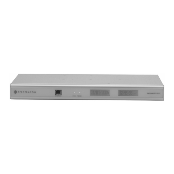
Refer to Figure 4-1 for a picture of the front panel. The Spectracom NetClock Master Clock has two main status LED’s present on the front panel. These status lights provide the user with the indication that power is applied to the unit (Power LED) and that the NetClock is currently synchronized or not synchronized (Sync LED). -
Page 142: Figure 4-1: Front Panel Display
Figure 4-1: Front panel display Page 4-2 Model 9183 Instruction Manual... -
Page 143: Status Indicator
(consult factory) Yellow LAN Activity detected. Ethernet No LAN traffic detected. (left) Green LAN Link established 10 or 100 Mb/s. Ethernet No link established. (right) Table 4-1: Status Indicator Model 9183 Instruction Manual Page 4-3... -
Page 144: Rear Panel
IRIG is a BNC output that provides an IRIG signal for synchronizing certain model voice recorders. 1PPS is a BNC output providing a once-per-second squarewave output. FREQ OUT is a BNC output providing a 10MHz sinewave output. Page 4-4 Model 9183 Instruction Manual... -
Page 145: Figure 4-2: Rear Panel Illustration
Figure 4-2: Rear panel illustration Model 9183 Instruction Manual Page 4-5... -
Page 146: Leap Second Occurrence
Add a Leap Second and 10b (2) for remove a Leap Second. The bit pattern 11b (3) indicates out of sync and in this condition NTP does NOT indicate Leap seconds. The Sync state indicates leap seconds by indicating sync can be 00b, 01b, or 02b. Page 4-6 Model 9183 Instruction Manual... -
Page 147: Sequence Of A Leap Second Correction Being Applied
4.3.3 Sequence of a Leap Second correction being applied 1. The following is the time output sequence that the Model 9183 will utilize to apply the Leap second at UTC midnight (Not local time midnight. The Local time at which the adjustment is made will depend on which Time Zone you are located in). - Page 148 Leap second inserted at end of month. B) An example log entry for a Negative Leap Second is as follows: TIME= 23:59:59 DATE= 2005-12-31 System Clock Service Leap second removed at end of month. Page 4-8 Model 9183 Instruction Manual...
-
Page 149: Troubleshooting
Contact Customer Service On Self Test (POST) then the indicator will blink in a sequence indicating the failure code (consult factory) Table 5-1: Status of Front Panel Power and Sync lampsFront Panel LAN Connector Model 9183 Instruction Manual Page 5-1... -
Page 150: Table 5-2: Status Of Front Panel Lan Connector
. This program will allow you to www.dillobits.com configure the view the raw NTP data to verify that the NetClock unit but can’t is outputting time data. Refer to the Spectracom synchronize website Support page for additional information on any PC’s with YATS32. -
Page 151: Verify Operation Of A Serial Port
Verify operation of a Spectracom TimeTap If you want to verify the operation of a Spectracom TimeTap, follow the same process as Section 5.2, but instead of connecting a serial cable into the PC, connect the TimeTap directly to the Serial comm port on the PC (A DB9 to DB25 adapter is required to verify operation of a Model 8178T TimeTap). -
Page 152: No Gps Reception
Window Type: Windows with metal film coatings, metal screens or blinds may impede GPS reception. If a window-mount antenna is being used, place the unit into the single satellite mode of operation. Refer to Section 3-22 for more information. Page 5-4 Model 9183 Instruction Manual... -
Page 153: Low Gps Quality
Window Type: Windows with metal film coatings, metal screens or blinds may reduce GPS reception. If a window-mount antenna is being used, place the unit into the single satellite mode of operation. Refer to Section 3-22 for more information. Model 9183 Instruction Manual Page 5-5... -
Page 154: Modem Dial-Out (Option 3) Troubleshooting
5) Type atz <enter> to reset the modem settings. 6) Type atm1 <enter> to turn the modem speaker on (When the modem is connected to the Spectracom clock, the unit will always disable the speaker if software is version 2.1.6 or below). - Page 155 53215 04-07-29 12:45:57 50 0 -.5 045.0 UTC(NIST) * 53215 04-07-29 12:45:58 50 0 -.5 045.0 UTC(NIST) * 53215 04-07-29 12:45:59 50 0 -.5 045.0 UTC(NIST) * 53215 04-07-29 12:46:00 50 0 -.5 045.0 UTC(NIST) * Model 9183 Instruction Manual Page 5-7...
-
Page 156: Test 2: To Verify Operation Of The Modem While Connected To The Netclock
5.5.2 Test 2: To verify operation of the modem while connected to the NetClock Below is the verification that the modem is properly being controlled by the Spectracom Master Clock and the modem is successfully dialing and connecting to NIST. - Page 157 TIME= 12:52:47 DATE= 2004-07-29 (First response) Modem dial out to 9 1-303-494-4774. TIME= 12:52:47 DATE= 2004-07-29 Timeout occurs, operation is aborted. Model 9183 Instruction Manual Page 5-9...
-
Page 158: Customer Service
Note: There are two responses because the “retry call” default (In the modem dial-out configuration page) is set to twice. Customer Service Refer to Section 1.2, Warranty Information and Product Support for information on contacting Page 5-10 Model 9183 Instruction Manual... -
Page 159: Serial Data Formats
During the 24-hour period preceding the change into DST During periods of Daylight Saving Time for the selected DST schedule During the 24-hour period preceding the change out of DST Example: 271 12:45:36 DTZ=08 Model 9183 Instruction Manual Page 6-1... - Page 160 The example data stream provides the following information: Sync Status: Time synchronized to GPS Date: Day 271 Time: 12:45:36 Pacific Daylight Time D = DST, Time Zone 08 = Pacific Time Page 6-2 Model 9183 Instruction Manual...
-
Page 161: Format 2
The example data stream provides the following information: Sync Status: The clock is not time synchronized to GPS. Time is derived from the battery backed clock or set manually Date: Friday, April 20, 2001 Time: 12:45:36 Model 9183 Instruction Manual Page 6-3... - Page 162 [1/2] 1 <enter> (Where 1 or 2 is the desired Remote port number). To change Data Format 1 output on a Remote RS-485 back to a leading space, type: rem fmt [1/2] 1 <enter> (Where 1 or 2 is the desired Remote port number). Page 6-4 Model 9183 Instruction Manual...
- Page 163 Indicators lists the quality indicators and the corresponding error estimates based upon the GPS receiver 1 PPS stability, and the time elapsed tracking no satellites. The Tracking Zero Satellites timer and the quality indicator reset when the receiver reacquires a satellite. Model 9183 Instruction Manual Page 6-5...
-
Page 164: Table 6-1: Table Of Quality Indicators
Sync Status: The clock has lost GPS time sync. The inaccuracy code of “A” indicates the expected time error is <10 milliseconds. Date: Day 271 of year 2001. Time: 12:45:36 UTC time, Standard time is in effect. Page 6-6 Model 9183 Instruction Manual... - Page 165 During periods of standard time for the selected DST schedule. During the 24-hour period preceding the change into DST. During periods of Daylight Saving Time for the selected DST schedule. During the 24-hour period preceding the change out of DST. Model 9183 Instruction Manual Page 6-7...
- Page 166 Sync Status: Time Synchronized to GPS. Date: April 15, 2001. Time: 12:45:36 EDT (Eastern Daylight Time). The time difference is 5 hours behind UTC. Leap Second: No leap second is scheduled for this month. Page 6-8 Model 9183 Instruction Manual...
- Page 167 The example data stream provides the following information: Data format: Sync Status: Time synchronized to GPS. Modified Julian Date: 50085 Time: 12:45:36.1942 UTC Leap Second: A leap second is scheduled at the end of the month. Model 9183 Instruction Manual Page 6-9...
- Page 168 During periods of Standard time for the selected DST schedule. During the 24-hour period preceding the change into DST. During periods of Daylight Saving Time for the selected DST schedule. During the 24-hour period preceding the change out of DST. Page 6-10 Model 9183 Instruction Manual...
- Page 169 Example: ? 01 271 12:45:36.123 S The example data stream provides the following information: Sync Status: The clock has lost GPS time sync. Date: Day 271 of year 2001. Time: 12:45:36 UTC time, Standard time is in effect. Model 9183 Instruction Manual Page 6-11...
- Page 170 = ? when the Master Clock has not achieved or has lost synchronization to UTC source. The time and date can be set to either local time or UTC time depending upon the configuration of the output port. Page 6-12 Model 9183 Instruction Manual...
- Page 171 The example data stream provides the following information: Time of Position Fix: 15:11:19.00 UTC Latitude: 43° 07.0241’ North Longitude: 77° 29.2249’ West Quality: 3D fix Satellites Used: Dilution of Precision: Antenna Height: +125.5 meters above sea level Check Sum: Model 9183 Instruction Manual Page 6-13...
- Page 172 Page 6-14 Model 9183 Instruction Manual...
-
Page 173: Setup Port Commands
Sets the subnet mask net show Shows network parameter net http Enable/disables http access to the unit 7.20 Enables options 7.21 reboot Reboots the unit 7.22 Configures the Remote RS-485 output(s) 7.23 Security Commands 7.24 Model 9183 Instruction Manual Page 7-1... -
Page 174: Table 7-1: Alphabetical List Of Commands
Displays summaries of the update subcommands Table 7-1: Alphabetical List of Commands NOTE: The commands shown in this section are all in lower case format. The NetClock accepts commands in upper or lower case formats. Page 7-2 Model 9183 Instruction Manual... -
Page 175: Fpd
- Date and Time display doy_time - Day of Year and Time display fpd date [format]<enter> Selects date format for LCD Displays format : Date Format selected from available choices below. MM_DD_YY DD_MM_YY YY_MM_DD MM_DD_YYYY Model 9183 Instruction Manual Page 7-3... - Page 176 Sets selected LCD Display's Local Time Clock by index fpd print lcd row col text <enter> Prints text string on lcd at desired location [0|1] : LCD Number row : Y location col : X location text : string to print Page 7-4 Model 9183 Instruction Manual...
-
Page 177: Frq
10MHz mode Set Signature Control Mode of operation status View Signature Control status none No Signature Control enabled major Major Alarm will disable frequency output sync Loss of time sync will disable frequency output Model 9183 Instruction Manual Page 7-5... -
Page 178: Help
Example, The current working directory is /test and it contains a file named data.txt. Follow the example below to display help about the net command. Type: help net <ent> Response: the 'net' group of commands is used to access and manage the network interface Page 7-6 Model 9183 Instruction Manual... -
Page 179: Irig
= reference clock index. 0 - UTC, 1-5 local clock Use 'ltc disp' to see the available clocks irig sig <none|sync> <enter> Sets the signature control of the IRIG port. none = no signature control sync = synchonized signature control Model 9183 Instruction Manual Page 7-7... -
Page 180: Login
Follow the example below to log in to the unit at the config security level. Type: login config <enter> Response: Password: Type PASSWORD<enter> (the terminal will not show what you type) Response: Login Successful Security Level is now: Config Level Page 7-8 Model 9183 Instruction Manual... -
Page 181: Logout
The logout command is available at the user security level. To log out of the unit to the user security level, issue the logout command as shown below: Type: logout <enter> Response: Logout Successful now at: User Level Model 9183 Instruction Manual Page 7-9... -
Page 182: Ltc
2 - North America 3 - Australia-1 4 - Australia-2 bwd IN <W> <DDD> <MMM> <HH:MM> <hh:mm> OUT <W> <DDD> <MMM> <HH:MM> <enter> Defines DST rule by week of month and day of week. Page 7-10 Model 9183 Instruction Manual... - Page 183 IN <MM> <DD> <HH:MM> <hh:mm> OUT <MM> <DD> <HH:MM> <enter> Defines DST rule by date. MM = Month; 01-12 DD = Day of month; 01-31 HH:MM = Time change; hours:minutes 00:00-23:59 local time hh:mm = Amount of change; hours:minute 00:00-23:59 Model 9183 Instruction Manual Page 7-11...
-
Page 184: Mdo
View or reset the modem statistics. If no argument is specified the statistics are printed to the console. If the reset argument is used the statistics are reset Example: mdo stat The system resets all stats on boot Page 7-12 Model 9183 Instruction Manual... -
Page 185: Net
[yes,no] [address] – enable gateway net mac [xx:xx:xx:xx:xx:xx] - get or set MAC address http net http [yes,no] – enable or disable http access to the unit The following are the set of subcommands for the net command: Model 9183 Instruction Manual Page 7-13... -
Page 186: Net Gateway
PASSWORD <ent> (the terminal will not show what you type) Response: Login Successful Security Level is now: Config Level Where: PASSWORD = The password for config security level. Type: net gateway yes GATEWAY_ADDRESS <ent> Response: Enabling default gateway: GATEWAY_ADDRESS Page 7-14 Model 9183 Instruction Manual... - Page 187 NOTE: Attempting to enable or set a gateway with an invalid IP address or an IP address that is not on the same subnet will result in an error. Be sure the desired gateway exists and is reachable on the LAN before setting/enabling it with the net gateway subcommand. Model 9183 Instruction Manual Page 7-15...
-
Page 188: Net Help
- display network configuration to the user default net default - set all net parameters back to default values gateway net gateway [yes,no] [address] – enable gateway net mac [xx:xx:xx:xx:xx:xx] - get or set MAC address Page 7-16 Model 9183 Instruction Manual... -
Page 189: Net Ip
Setting new address: 192.168.0.100 Stack IP address: 192.168.0.100 New IP address set NOTE: The Stack IP address reflects the value that the TCP/IP stack is set to. This should match the IP address being set. Model 9183 Instruction Manual Page 7-17... -
Page 190: Net Mac
Type: net mac <ent> Response: MAC address: XX;XX;XX;XX;XX;XX Where: XX;XX;XX;XX;XX;XX = The Ethernet MAC address for the unit. Note: The MAC address of the NetClock is configured at the factory and cannot be changed. Page 7-18 Model 9183 Instruction Manual... -
Page 191: Net Mask
Setting new netmask: 255.255.0.0 Stack netmask: 255.255.0.0 New netmask Has been set NOTE: The Stack netmask reflects the value that the TCP/IP stack is set to. This should match the netmask value being set. Model 9183 Instruction Manual Page 7-19... -
Page 192: Net Show
The net subcommand, http, is used to enable or disable the HTTP protocol. The http subcommand is available at the administrator security level only. To display the current http setting, issue the http subcommand as shown below: Page 7-20 Model 9183 Instruction Manual... - Page 193 <ent> (the terminal will not show what you type) Response: Login Successful Security Level is now: Admin Level Where: PASSWORD = The password for admin security level. Type: net http yes <ent> Response: HTTP Enabled Model 9183 Instruction Manual Page 7-21...
-
Page 194: Opt
Serial Port 2: Remote Port 2: IRIG Output: Front Panel: Relays: Oscillator Disciplining: ON 10 MHz Frequency Output: ON Serial Time Code Input: OFF SNTP Server: Oscillator Type: TCXO GPS Receiver: Motorola M12T Board: NONE Page 7-22 Model 9183 Instruction Manual... -
Page 195: Reboot [Bootloader]
/sys/bin/. If either of these conditions is not fulfilled, the unit may fail to boot the application image, which could result in a unit that function incorrectly or not at all. Model 9183 Instruction Manual Page 7-23... -
Page 196: Rem
: The remote serial port to configure (1 or 2) baud : Baud rate; 1200, 2400, 4800, 9600 format: Format of output 00, 01, 02, 03, 04, 06, 07, 08, 90 clock : Reference clock. 0 - UTC, 1-5 local clocks Page 7-24 Model 9183 Instruction Manual... -
Page 197: Sec
- show the current security level password sec password <Account-Name> help sec help - list of sec sub-commands and detailed information on each The following are the set of subcommands for the sec command: Model 9183 Instruction Manual Page 7-25... -
Page 198: Sec Help
<ent> Response: account sec account <Account-Name> <new-name> level sec level - show the current security level password sec password <Account-Name> help sec help - list of sec sub-commands and detailed information on each Page 7-26 Model 9183 Instruction Manual... -
Page 199: Sec Level
The sec subcommand, level is used to show the current security level. The level subcommand is available at the user security level. To show the current security level, issue the level subcommand as shown below: Type: sec level <ent> Response: Security Level is: User Level Model 9183 Instruction Manual Page 7-27... -
Page 200: Sec Password
Old Password: Type: [current password for this account] <ent> Response: New Password: Type: [New password for this account] <ent> Response: New Password (again): Type: [New password for this account] <ent> Response: New Password set Page 7-28 Model 9183 Instruction Manual... -
Page 201: Ser
Baud rate; 1200, 2400, 4800, 9600 format: Format of output 00, 01, 02, 03, 04, 06, 07, 08, 90 req: Request character. Use none for multicast clock: Reference clock. 0 - UTC, 1-5 local clocks Model 9183 Instruction Manual Page 7-29... -
Page 202: Update
<filename> - install a new bootload image update app <filename> - install a new application kern update kern <filename> - install a new kernel The following are the set of subcommands for the update command: Page 7-30 Model 9183 Instruction Manual... -
Page 203: Update App
If a non-application image is installed it can be overwritten by re-updating with a correct application image. The unit will operate incorrectly or completely fail to run if this command is not used with care. Model 9183 Instruction Manual Page 7-31... -
Page 204: Update Boot
If a non-bootloader image is installed it can be overwritten by re-updating with a correct bootloader image. The unit will operate incorrectly or completely fail to run if this command is not used with care. Page 7-32 Model 9183 Instruction Manual... -
Page 205: Update Csl
CSL images. If a non-CSL image is installed it can be overwritten by re- updating with a correct CSL image. The unit will operate incorrectly or completely fail to run if this command is not used with care. Model 9183 Instruction Manual Page 7-33... -
Page 206: Update Kern
If a non-kernel image is installed it can be overwritten by re- updating with a correct kernel image. The unit will operate incorrectly or completely fail to run if this command is not used with care. Page 7-34 Model 9183 Instruction Manual... -
Page 207: Update Help
<filename> - install a new CSL image boot update boot <filename> - install a new bootload image update app <filename> - install a new application kern update kern <filename> - install a new kernel Model 9183 Instruction Manual Page 7-35... - Page 208 Page 7-36 Model 9183 Instruction Manual...
-
Page 209: Options
The following table provides the standard configurations for the Model 9183 and the options that may be purchased and installed in the field. -
Page 210: Modem Installation
Spectracom supplied compatible modem. Note: The modem MUST be Hayes AT compatible and configured for this mode of operation to operate correctly with the unit. The Spectracom supplied modem is Hayes AT compatible. 8.1.2 Modem installation The cable needed to connect the modem to the NetClock is a DB9 male to DB25 male null modem serial cable. -
Page 211: Calibration Call
No changes will be made to the system time. Testing can be done only in sync from another time source and can either be on a specified interval or as requested. Model 9183 Instruction Manual Page 8-3... -
Page 212: Modem Dial-Out Configure Page
Modem Mode: In this mode, the Serial Setup port can be connected to a modem for dialing out. The Serial Setup port will be unavailable for network configuration while in this mode. Important Note: The unit must be rebooted to apply the changes made to the serial setup port mode. Page 8-4 Model 9183 Instruction Manual... - Page 213 When a unit is configured in modem mode while it is in time sync, the “Dialout now” checkbox will be greyed-out (disabled). Modem speaker: Toggles the modem speaker on or off during dial out. Model 9183 Instruction Manual Page 8-5...
-
Page 214: Modem Dial-Out Dialout Page
8.1.9 Modem Dial-out DIALOUT page Figure 8-2: Modem Dial-Out DIALOUT Configure Screen Page 8-6 Model 9183 Instruction Manual... - Page 215 Changing the timer’s settings to 30 minutes will not affect the current countdown. The new 30 minutes value will only be used if another power cycle occurred). If want to skip the initial countdown, you can always use the Dialout Now feature. Model 9183 Instruction Manual Page 8-7...
-
Page 216: Modem Dial-Out Calibrate Page
If the modem is strictly a backup to the external reference, this period can be lengthened to longer than the typical amount of time needed to synchronize to the external reference. 8.1.10 Modem Dial-out CALIBRATE page Figure 8-3: Modem Dial-Out CALIBRATE Screen Page 8-8 Model 9183 Instruction Manual... - Page 217 This should not be lowered from the default, but it may be safely raised. Calibration Call Interval: This is the interval between calibration calls. This value, along with the number of calibration calls, will determine how long the calibration process will take. Model 9183 Instruction Manual Page 8-9...
-
Page 218: Modem Dial-Out Test Page
8.1.11 Modem Dial-out TEST page Figure 8-4: Modem Dial-Out TEST Screen Page 8-10 Model 9183 Instruction Manual... - Page 219 Change the modem speaker radio button settings to on. Review the changes made and click Submit. The browser will ask for the unit to be rebooted to apply the changes to the setup serial port mode. Model 9183 Instruction Manual Page 8-11...
- Page 220 Use this information to connect to the unit through telnet or the web browser user interface to communicate with the unit. Note: For additional assistance with troubleshooting the modem functionality, please refer to Section 5.5. Page 8-12 Model 9183 Instruction Manual...
-
Page 221: Option 4: Rubidium Oscillator
0.18 microseconds / hour (nominal) 463 days OCXO Option 5 72 microseconds / hour (nominal) 28 hours TCXO Standard 1.0 milliseconds / hour (nominal) 2 hours (typical) TCXO Standard 7.2 milliseconds / hour (worst case) 17 minutes* Model 9183 Instruction Manual Page 8-13... -
Page 222: Option 5: Ocxo Oscillator
72 microseconds / hour (nominal) 28 hours Rubidium Option 4 0.18 microseconds / hour (nominal) 463 days TCXO Standard 1.0 milliseconds / hour (nominal) 2 hours (typical) TCXO Standard 7.2 milliseconds / hour (worst case) 17 minutes* Page 8-14 Model 9183 Instruction Manual... -
Page 223: Sw License Notices
29. [32]David L. Mills <mills@udel.edu> Version 4 foundation: clock discipline, authentication, precision kernel; clock drivers: [Tatu continues] Spectracom, Austron, Arbiter, Heath, ATOM, ACTS, KSI/Odetics; audio clock drivers: CHU, WWV/H, IRIG However, I am not implying to give any licenses to any patents or * copyrights held by third parties, and the software includes parts 30. - Page 224 The OpenSSL toolkit stays under a dual license, i.e. both the conditions * THIS SOFTWARE IS PROVIDED BY THE AUTHORS ''AS IS'' AND ANY the OpenSSL License and the original SSLeay license apply to the toolkit. EXPRESS Page 9-2 Model 9183 Instruction Manual...
- Page 225 Redistributions in binary form must reproduce the above copyright the apps directory (application code) you must include an notice, this list of conditions and the following disclaimer in the acknowledgement: documentation and/or other materials provided with the distribution. Model 9183 Instruction Manual Page 9-3...
- Page 226 Sections 1 and 2 above on a medium Redistributions of source code must retain the above copyright customarily used for software interchange notice, Page 9-4 Model 9183 Instruction Manual...
- Page 227 NETCLOCK MODEL 9183 MANUAL ADDENDUM SOFTWARE v2.3.0 TO v2.3.1 95 Methodist Hill Drive Rochester, NY 14623 Phone: 585.321.5800 Fax: 585.321.5219 www.spectracomcorp.com Part Number 9183-5001-0050 Manual Addendum 22 December 2005...
- Page 228 Copyright © 2005 Spectracom Corporation. The contents of this publication may not be reproduced in any form without the written permission of Spectracom Corporation. Printed in USA. Specifications subject to change or improvement without notice. Spectracom, NetClock, Ageless, TimeGuard, TimeBurst, TimeTap, LineTap, MultiTap, VersaTap, and Legally Traceable Time are Spectracom registered trademarks.
- Page 229 Spectracom’s judgment the defective condition in a Spectracom Spectracom be liable for any direct, indirect, special or product is for a cause listed above for which Spectracom is not consequential damages whether the claims are grounded in responsible, Spectracom will make the repairs or replacement of contract, tort (including negligence), or strict liability.
- Page 231 Spectracom Corporation 9183 – v2.3.1 Table of Contents CHANGES FOR V2.3.0 TO V2.3.1 ............1-1 NETWORK AND WEB USER INTERFACE CHANGES ......... 2-1 Command Line Changes .......................2-2 2.1.1 net telnet ..........................2-2 2.1.2 net ftp............................2-2 2.1.3 net https ..........................2-2 2.1.4 net sshd (Includes SSH, SCP, and SFTP)................2-2 Web Server Timeout........................2-2...
- Page 232 9183 – v2.3.1 Spectracom Corporation 9183 v2.3.0 to v2.3.1 Addendum...
-
Page 233: Changes For V2.3.0 To V2.3.1
This addendum to the operations and maintenance manuals for the Spectracom ® NetClock Model 9183 (current to software version 2.3.0) describes the changes made to software features for version 2.3.1. These changes include additions and enhancements to the Web User Interface (Web UI), to the command line, and in SNMP. -
Page 234: Command Line Changes
Web UI session using telnet or ssh. Also added is a command to set the timeout to a user-defined value, which means users may now dictate the length of time it takes for the session to expire. 9183 v2.3.0 to v2.3.1 Addendum... -
Page 235: Web Exit
2.2.2 web timeout This command allows the user to set the web session timeout to any value between 1 and 60 minutes (inclusive). Spectracom recommends selecting a timeout interval of 10 to 15 minutes. 9183 v2.3.0 to v2.3.1 Addendum... -
Page 236: Https Certificate 20-Year Life
(with a red asterisk). Refer to the Security tab on the System Setup page. The default Spectracom HTTPS Web Server Certificate is now 20 years. The new default Certificate life is therefore 7300 days (20 years, in days) and appears on the... -
Page 237: Modem
The baud rates 1200 and 9600 are supported because they are the most commonly used baud rates for ITU-R and ACTS formats worldwide. ITU-R format typically uses 1200 baud, while ACTS format typically uses 9600 baud. Figure 2-3: Baud Rate Support 9183 v2.3.0 to v2.3.1 Addendum... -
Page 238: Setup Serial Port Mode
To switch from Serial Console Port mode, select Modem mode (Figure 2-4). Once the Modem mode is selected, click Modem Dial Out (Figure 2-5). This displays all the modem tabs. Figure 2-4: Switching from Console Mode to Modem Mode 9183 v2.3.0 to v2.3.1 Addendum... - Page 239 Spectracom Corporation 9183 – v2.3.1 Figure 2-5: Modem Dial Out 9183 v2.3.0 to v2.3.1 Addendum...
-
Page 240: Modem Command Line Commands
NOTE: Do not leave this mode switched on, as the number of log files increases with each call. Switch it on as directed by Spectracom if you are testing a new dial- up time service. Enter mdo log debug to switch the log on. Enter mdo log normal to switch the log off. - Page 241 9600 baud. NIST ACTS may support either, but 9600 baud is recommended. 2.4.3.8 mdo speaker Entering this command switches the modem speaker on and off. Enter mdo speaker on to enable the speaker and mdo speaker off to disable it. 9183 v2.3.0 to v2.3.1 Addendum...
-
Page 242: Ntp
NetClock, such as NYC, CHI, BOS, etc. Refer to Figure 2-6. Figure 2-6: Reference Identifier Field Spectracom provides a means to set a Reference Identifier for the primary time sources, such as GPS, Serial Time Code Input, or User Defined. A means to define the 2-10... -
Page 243: Ntp Command Line
Setting the time manually means the unit is NOT traceable to UTC. When entering time manually, you MUST use UTC time. If you enter local time (or a time from any other time zone), the time will be misinterpreted as UTC. 9183 v2.3.0 to v2.3.1 Addendum 2-11... -
Page 244: Further Assistance
Figure 2-7: Setting System Time Options 2.7 Further Assistance If you require additional assistance integrating this addendum with your operations and maintenance manual(s), please contact Spectracom Customer Service 585.321.5800. Spectracom may also be reached through our website at www.spectracomcorp.com. 2-12 9183 v2.3.0 to v2.3.1 Addendum... - Page 246 Spectracom Corporation 95 Methodist Hill Drive Rochester, NY 14623 www.spectracomcorp.com Phone: 585.321.5800 Fax: 585.321.5219...
Need help?
Do you have a question about the 9183 and is the answer not in the manual?
Questions and answers