Sign In
Upload
Manuals
Brands
Spectracom Manuals
Clock
9183
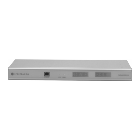
Spectracom 9183 GPS Master Clock Manuals
Manuals and User Guides for Spectracom 9183 GPS Master Clock. We have
1
Spectracom 9183 GPS Master Clock manual available for free PDF download: Instruction Manual
Spectracom 9183 Instruction Manual (246 pages)
NetClock/GPS Master Clock
Brand:
Spectracom
| Category:
Clock
| Size: 7 MB
Table of Contents
Section 1
4
Table of Contents
4
General Information
11
Introduction
11
Warranty Information and Product Support
12
Unpacking
13
Package Contents
13
Protocols Supported
14
10/100 Ethernet Port
14
Serial Setup Interface Port
14
Receiver
14
Model 9183 Specifications
14
Communication Port
15
Output
15
Front Panel Display
16
Front Panel LED Indicators
16
Relay Outputs
16
IRIG Output
16
1PPS Output
17
Frequency Output
17
Input Power
18
Mechanical and Environmental
18
Agency Approvals
18
Installation
19
Installation Summary
19
Table 2-1: Time Zone Offsets Available for Data Outputs
20
Required Tools and Cables
21
Power and Ground Connection
21
GPS Antenna Installation
22
Antenna Cable for Outdoor Antenna
22
Cable Lengths
22
Model 8224 GPS Splitter
23
Model 8226 Impulse Suppressor
23
Figure 2-1: Cabling Recommendations
23
Figure 2-3: Model 8227 Inline Amplifier
24
Figure 2-2: Model 8226 Impulse Suppressor
24
Model 8227 GPS Inline Amplifier
24
Ethernet Network Cabling
25
Optional CNC3000 Cable Kit
25
Remote Port and Serial Comm Port Output Pin-Outs and Wiring
26
Serial Comm Ports
26
Figure 2-4: Serial Port Connector
26
Remote Port
27
Figure 2-5: Remote Outputs
27
Table 2-2: Serial Port Pin Assignments
27
Remote Output Usage
28
Guidelines
28
Figure 2-6: RS-485 Output
28
Table 2-3: Cable Sources for RS-485 Lines over 1500 Feet
28
Connection Method
29
Figure 2-7: One-Way Bus Installation
29
Table 2-4: Cable Sources for RS-485 Lines under 1500 Feet
29
Figure 2-8: Split Bus Configuration
30
Figure 2-9: Wire Strain Relief
31
Figure 2-10: Timeview RS-485 Interface
32
Figure 2-11: Model 8179T Timetap RS-485 Interface
32
Figure 2-12: Model 9188 RS-485 Interface
33
Figure 2-13: Timeburst RS-485 Interface
33
Termination
34
Product Configuration
35
Network Configuration
35
To Configure the Product to Work on a Network Via the Serial Setup Port
36
Figure 3-1: Serial Setup Interface Port Connector
36
Initial Network Setup
37
Default and Recommended Configurations
40
Login
41
Figure 3-2: Log-In Permissions
42
Figure 3-3: Configuration Mode Log-In
43
Figure 3-4: Administrator Mode Log-In
43
To Change the Default Login Password Values
44
To Reset the Current Login Password Values Back to the Factory Default Values
45
Alarms
46
Alarm Outputs
46
Alarm Log
46
Figure 3-5: Alarm Setup Screen
47
Event Timer
48
Configuring the Event Timer
48
Figure 3-6: Event Timer Relay Screen
48
Figure 3-7: Event Timer Relay Screen
49
Front Panel Display
52
Figure 3-8: Front Panel Display Screen
52
Gps
55
Figure 3-9: GPS Set-Up Screen
55
Set System Mode
56
Figure 3-10: Set System Mode
57
Figure 3-11: GPS Signal Status Setup Screen
58
GPS Signal Status
58
Interface Setup
63
Configuration Parameters for the Remote and Serial Interfaces
63
Figure 3-12: Interface Screen
64
Set to Defaults" Web Browser User Interface
65
Figure 3-13: Restore Interface Setup Back to Factory Defaults
66
IRIG Port
67
Figure 3-14: IRIG Screen
67
Figure 3-15: IRIG Output Level
68
IRIG B Output
70
Figure 3-16: IRIG B Time Code Description
70
Table 3-3: IRIG B Control Function Field
72
IRIG E Output
73
Figure 3-17: IRIG E Time Code Description
75
Table 3-4: IRIG E Control Function Field
77
Local System Clocks Setup
78
Figure 3-18: Local System Clocks Setup Screen
78
Figure 3-19: Time Zone and DST Setup Screen
79
Time Zone and DST
81
Logs
84
Table 3-5: Descriptions of Logs
84
Display Alarm Log
85
Display Dial-Out Log (Applicable Only to Units with Option 3 - Modem)
86
Display Event Relay Log
89
GPS Qualification Log
89
Display Operational Log
91
Display Oscillator Log
93
Ntp/Sntp
96
Configure NTP
96
Figure 3-20: NTP Screen
96
NTP Support
98
Application Note: MD5 Authentication Using a Cisco Router
98
NTP Statistics
99
Figure 3-21: NTP Statistics
99
Figure 3-22: Relay Output Screen
102
Relays
102
Configuring the Relays
102
Security
104
Security Overview
104
Configuring SSH
104
Figure 3-23: SSH Configuration Screen
105
Figure 3-24: Creating SSH Host Key Files
106
Figure 3-25: Selecting SSH Authentication Modes
108
Figure 3-26: Adding SSH Public Key to Authorized Keys
109
Figure 3-27: Adding a New SSH Public Key File
111
Configuring HTTPS
114
Restoring Self Signed Certificates and Private Keys
115
Figure 3-28: Deleting SSL Certificate, Certificate Request and Private Key Files
115
Figure 3-29: Restoring User's Self Signed Certificate and Private Key Files
115
Creating Self Signed Certificates, a Private Key, and a Certificate Request
116
Figure 3-30: Creating a New Certificate Request and Self Signed Certificate
116
Figure 3-31: a New Certificate Request and Self Signed Certificate
117
Requesting Certificate Authority Certificates
117
Installing Certificates
118
Figure 3-32: Installing a New Certificate
118
Using Externally Generated Certificates
119
What to Do if You Cannot Get into a Secure Spectracom Product
120
Figure 3-33: Using External Certificate
120
Signature Control for the Frequency Output
122
Figure 3-34: Signature Control Configuration Page
123
Snmp
124
SNMP Configuration
124
Figure 3-35: Snmpv1 Setup Screen
124
Spectracom MIB
129
SNMP Support
129
System Status
130
Dynamic System Information
130
Static System Information
131
System Test Results
131
System Features and Options
133
System Time
134
Figure 3-36: System Time
134
Variable Holdover
136
Table 3-6: Estimated Oscillator Error Rates
136
Table 3-7: Minimum and Maximum Allowable Holdover Values
136
Setting the Variable Holdover Value for a TCXO Oscillator
137
Figure 3-37: TCXO Variable Holdover Configuration
137
Figure 3-38: OCXO and Rb Oscillator Variable Holdover Configuration
138
Setting the Variable Holdover Value for an OCXO or Rubidium Oscillator
138
Operation
141
Front Panel
141
Figure 4-1: Front Panel Display
142
Status Indicator
143
Table 4-1: Status Indicator
143
Rear Panel
144
Figure 4-2: Rear Panel Illustration
145
Leap Second Alert Notification
146
Leap Second Occurrence
146
Reasons for a Leap Second Correction
146
Sequence of a Leap Second Correction Being Applied
147
Figure 4-3: Negative Leap Second Indication
147
Figure 4-4: Positive Leap Second Indication
147
Troubleshooting
149
Front Panel Power and Sync Lamps
149
Table 5-1: Status of Front Panel Power and Sync Lampsfront Panel LAN Connector
149
Table 5-2: Status of Front Panel LAN Connector
150
Verify Operation of a Serial Port
151
Verify Operation of a Spectracom Timetap
151
GPS Reception
151
No GPS Reception
152
Table 5-3: Typical Antenna Cable Resistance Values
152
Low GPS Quality
153
Modem Dial-Out (Option 3) Troubleshooting
154
Test 1: to Verify Modem Is Dialing and Connecting to NIST in Stand- Alone Mode:5-6
154
Test 2: to Verify Operation of the Modem While Connected to the Netclock
156
Customer Service
158
Serial Data Formats
159
Format 1
159
Format 2
161
Format 3
161
Format 90
161
Table 6-1: Table of Quality Indicators
164
Setup Port Commands
173
Table 7-1: Alphabetical List of Commands
174
Fpd
175
Frq
177
Help
178
Irig
179
Login
180
Logout
181
Ltc
182
Mdo
184
Mdo Help <Enter
184
Mdo Avg <On|Off> <#|Auto> <Enter
184
Mdo Log <Normal|Debug> <Enter
184
Mdo Stat [Reset] <Enter
184
Net
185
Net Gateway
186
Net Help
188
Net Ip
189
Net Mac
190
Net Mask
191
Net Show
192
Net Http
192
Opt
194
Reboot [Bootloader]
195
Rem
196
Sec
197
Sec Help
198
Sec Level
199
Sec Password
200
Ser
201
Update
202
Update App
203
Update Boot
204
Update Csl
205
Update Kern
206
Update Help
207
Options
209
Option 3: Modem
209
Option 3 Basics
209
Modem Installation
210
Modem Dial-Out Setup
210
Modem Test Call
211
Time Sync Call
211
Time Verification Call
211
Calibration Call
211
Modem Dial-Out CONFIGURE Page
212
Figure 8-1: Modem Dial-Out CONFIGURE Screen
212
Modem Dial-Out DIALOUT Page
214
Figure 8-2: Modem Dial-Out DIALOUT Configure Screen
214
Modem Dial-Out CALIBRATE Page
216
Figure 8-3: Modem Dial-Out CALIBRATE Screen
216
Figure 8-4: Modem Dial-Out TEST Screen
218
Modem Dial-Out TEST Page
218
Option 4: Rubidium Oscillator
221
Comparison of the Rubidium Oscillator to the OCXO and Standard TCXO Oscillators
221
Option 5: OCXO Oscillator
222
Comparison of the OCXO to the Rubidium and Standard TCXO Oscillators
222
Sw License Notices
223
Section 2
231
Changes for V2.3.0 to V2.3.1
233
Network and Web User Interface Changes
233
Command Line Changes
234
Net Ftp
234
Net Https
234
Net Sshd (Includes SSH, SCP, and SFTP)
234
Net Telnet
234
Web Server Timeout
234
Web Exit
235
Web Timeout
235
HTTPS Certificate 20-Year Life
236
Baud Rate
237
Modem
237
Setup Serial Port Mode
238
Modem Command Line Commands
240
Ntp
242
NTP Command Line
243
System Time
243
Further Assistance
244
Advertisement
Advertisement
Related Products
Spectracom 9289
Spectracom NetClock 9483
Spectracom NetClock 9400 Series
Spectracom NetClock 9489
Spectracom 8175
Spectracom 8183A GTP
Spectracom 8183A NETCLOCK
Spectracom EPSILON EC1S
Spectracom NetClock
Spectracom TimeView 230
Spectracom Categories
Clock
Server
Test Equipment
Computer Hardware
Switch
More Spectracom Manuals
Login
Sign In
OR
Sign in with Facebook
Sign in with Google
Upload manual
Upload from disk
Upload from URL