Advertisement
Project4
7/27/04
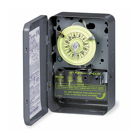
MODEL: T185
24 HOUR DIAL TIME SWITCH
WITH ADJUSTABLE TRIPPERS
ONE NORMALLY OPEN -ONE NORMALLY CLOSED CONTACTS
MAY BE WIRED AS SINGLE POLE DOUBLE THROW.
40 AMP. RESISTIVE, INDUCTIVE, TUNGSTEN
OR 1000 VA, PILOT DUTY - 120-277 VOLT AC;
2 HP (24 FLA) - 120V. AC; 5 HP (28 FLA) - 240V AC.
CLOCK MOTOR VOLTAGE AND CYCLE MUST BE AS SPECIFIED. TO
ORDER REPLACEMENT, INDICATE PART NO. (WG--) ON MOTOR COVER.
TRIPPER
TIME
POINTER
LEVER
FIGURE 1
WIRING INSTRUCTIONS:
To wire as SINGLE POLE NORMALLY OPEN, move motor lead from
terminal 3 to 1, and connect LINE to 1, LOAD to 2. To wire as SINGLE
POLE DOUBLE THROW, install jumper (the same gauge as LINE wire)
between terminals 2 and 3 and connect LINE to 2, LOADS to 1 and 4.
NOTE: Line 2 if present is uninterrupted. Use COPPER wire only. For
gauge selection and wire connection, see details below. Use 3//16 or larg-
er screwdriver, tighten terminal screws firmly (25lb-in minimum).
REPLACE FRONT INSULATOR BEFORE TURNING ON ELECTRICITY.
MAX.
MIN.
MINIMUM
LOAD
INSUL-
COPPER
ATION
WIRE SIZE
(AMP)
TEMP(°C)
(AWG)
14
15
60
12
20
60
10
60
30
8
75
40
PROGRAMMING INSTRUCTIONS
• TO SET TRIPPER(S): A. Loosen screw A. (Fig. 1 inset); move time
selector pointer to desired timing (scale is in minutes); tighten screw A.
Place TRIPPER(S) on CLOCK-DIAL at time(s) daily operation(s) is/are
to take place. Tighten screw B. firmly.
• TO SET TIME-OF-DAY: Pull CLOCK-DIAL outward. Turn in either
direction and align the exact time-of-day on the CLOCK-DIAL (the time
now, when switch is being put into operation) to the pointer. DO NOT
MOVE POINTER.
OPERATING INSTRUCTIONS
• TO OPERATE SWITCH MANUALLY: Move MANUAL LEVER below
CLOCK-DIAL left or right as indicated by arrows. This will not effect
next operation. NOTE: The MANUAL LEVER is inoperative for 15
minutes immediately after an automatic operation.
• IN CASE OF POWER FAILURE, reset CLOCK-DIAL to proper time-
of-day. See programming instructions.
INTERMATIC INCORPORATED
SPRING GROVE, ILLINOIS 60081-9698
158T10710
3:45 PM
CLOCK MOTOR: 110-125V. 60 HZ.
WIRING
CLOCK
DIAGRAM
DIAL
120V
SUPPLY
TYPICAL WIRING: SINGLE POLE NORMALLY CLOSED
SEE WIRING INSTRUCTIONS BELOW FOR OTHER TYPES
To wire switch follow diagram above.
75°C INSULATION MAX. MOTOR
LOAD (HP)
SINGLE PHASE
3 PHASE
120 V.
240 V.
208 V.
240 V.
2
1/2
2 1/2
1
N/A
N/A
2
3
5
-
Page 1
CLOCK
MOTOR
GRD.
A
1
N
LINE
LR3730
LISTED
885L
2
3
4
TO
LOAD
GROUND
PRESSURE PLATE
TERMINAL SCREW
MAKE SURE WIRE
INSULATION CLEARS
PRESSURE PLATE
Advertisement
Table of Contents


Need help?
Do you have a question about the T185 and is the answer not in the manual?
Questions and answers