
Related Manuals for Deger MLD Control Energy Converter S1


Summary of Contents for Deger MLD Control Energy Converter S1
- Page 1 ASSE MBLY Y INS STRUC CTION ontro nergy Conv verter 00-PF...
- Page 2 Copyright All information presented in this technical document and the drawings and technical descriptions made available by DEGER remain the property of DEGER and may not be reproduced without prior explicit written permission from DEGER. We reserve the right to make technical changes.
-
Page 3: Table Of Contents
List of contents Abbreviations ..............................5 Introduction ............................6 Basic safety information ........................6 Exclusion of liability ..........................6 For your safety ........................... 6 1.4.1 Intended purpose of the DEGERtracker ..................6 ... - Page 4 Climatic conditions ........................... 20 General ............................20 Troubleshooting ........................... 21 10.1 Troubleshooting diagram for Energy Converter EK-S1 ..............21 10.2 Fault report............................22 Maintenance ............................23 Cleaning ............................... 23 ...
-
Page 5: Abbreviations
Abbreviations Elevation(east-west orientation) Central Tracker Control (software) EK-S1 Energy Converter S1 Maximum Light Detection MLD Control Energy Converter, MLD sensor, wind sensor, snow sensor Personal Protective Equipment Uninterruptible power supply 18.04.2018 ASSEMBLY INSTRUCTIONS MLD CONTROL EK-S1 Page 5... -
Page 6: Introduction
The snow sensor shall not release the module surface from the obligation to be cleared of snow. DEGER recommends an Uninterruptible Power Supply (UPS) to ensure the function of the wind monitor. As a rule, DEGER’s General Terms and Conditions shall apply. The contents of these documents are checked continuously and modified as needed. -
Page 7: Symbols Used
The followin ng symbols a appear on the e DEGERtra acker and are e used in the present doc cument: No unau uthorized acc cess Read an nd follow the e operating m manuals and safety inform mation before e start-up 1.6.1 Lis sts andinst tructions... -
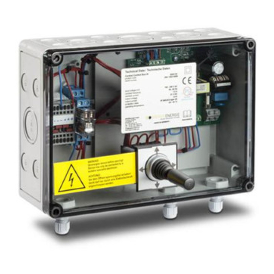
Page 8: Energy Converter S1 (Ek-S1)
2 Ene rgy Con nverter S S1 (EK-S Applies in general: 1. External i nput has prio ority over ML LD sensor. 2. External i nput from wi ind sensor h as priority ov ver external m manual cont trol. Reverse di rection func ction:... -
Page 9: Ek-S1: Pin Assignments
Terminal Function Wirec code Term minal Funct recode Drives 24 V Wind S Sensor Pin A => M otor 1+ Master Blue Pin A: => (+24V) re 5 Pin B => M Motor 1- Master Pin B: => Wind Signal re 4 Pin A =>... -
Page 10: Ek-S1 Led - Display
EK-S S1 LED– d display 2.4.1 LED D’s indicat ting main f functions: 1 - Wind sen nsor – Snow sen nsor en LED wind ok Gree en LED snow ok d LED wind alarm d LED snow alarm ... -
Page 11: 2.4.2 Led Assignments
2.4.2 LED assignments Multi-Color- Part Code Assignment Function Green: Moving to face west Red: Moving to face east Motor 1 active LED off: motor is off Green: Moving to face west Red: Moving to face east Motor 2 active LED off: motor is off Green: Irradiation west predominant MLD sensor Red: Irradiation east predominant... -
Page 12: Joystick Functions
3 Man nual Con ntrol Joys stickFunct tions The externa al Joystick ca an be plugge ed into socke et XJ1 during operation of f the EK-S1 a after removin ng the cover of the housi ing. Automat tic mode and d manual mo ode from CTC C is deactiva... -
Page 13: Wind Guard
4 Wind d Guard The wind al arm become es activated w when the win nd speed con ntinuously ex xceeds the d default setting g of 12 m/s. The alarm w will stop whe n the wind s peed is cont inuously slow wer than the default settin... -
Page 14: Snow Sensor
5 Snow w Senso Func ction The snowse ensordetects accumulatio ons of snow a and ice on theDEGE ERtracker. When a cer rtain amount of snow or ice accum mulates on th sensor, a si gnal is sent to the CTC, which h moves the s solar... -
Page 15: Assembly
sembly 1.The 20 cm m aluminum profile has to o be Clam mp plate mounted to the east side e of the mod dule surfaceusin g two bolts M M6, two clam plates and t two sliding n uts M6. Torque: 8 N Modul Sliding... -
Page 16: Connections
6 Con nections Bloc ck diagram __________ __________ ___________ ___________ __________ ___________ ___________ __________ __________ ANGER! nly trained a nd qualified personnel m may connect t the EK-S1 to o external de evices. __________ __________ ___________ ___________ __________ ___________ ___________ __________ __________ ANGER! -
Page 17: Can-Bus
N-Bus 6.2.1 CA AN-Bus con nnections E EK-S1 The EK-S1 offers two co onnections: C CAN Bus In (terminal XK K) and Can B us Out (term minal XL). The shieldin ng of the CA N-Bus cable s must be pr roperly stripp ped and fixed d into the me... -
Page 18: Can-Bus Connections Ek-S1
Unin nterruptibl e power s upply fora a DEGERtra acker It is possible e to provide an Uninterru uptible Power r Supply (UP PS) for a DEG GERtracker. The power p provided will move the D EGERtracke er in case of a power failu ure into safet ty position. -
Page 19: Start-Up
7 Star rt-up ANGER! lectrical cur rrent can be fatal! ontact with li ve compone ents can be fa atal due to e lectric shock T The external l voltage sup pply must me eet the region nal regulation ... -
Page 20: Technical Data
9 Technical Data Electrical ratings Nominal input voltage 100 to 240VAC/ 110-250VDC Line frequency 50 to 60 Hz Inrush current 30 A @ Tu 25 Input power 179W @ Uin= 230 VAC Nominal current 0,78 A Output voltage motors 24 VDC Nominal output current 3A (in Manual Control mode) Peak output current... -
Page 21: Troubleshooting
10 Trou ubleshoo oting 10.1 Trou ubleshooti ng diagram m for Ener rgy Conver rter EK-S1 __________ __________ ___________ ___________ __________ ___________ ___________ __________ __________ ANGER! When conducti ing tests on th he DEGERtra acker, ensure e that all parts s have been d disconnected from... -
Page 22: 10.2 Fault Report
10.2 Fault report DEGERtracker S100-PF-SR Serial No. EK-S1 Deliverydate Serial No..DEGERtracker Serial No. motor Single system Energy plant with …… systems Driven pile foundation Concrete foundation Problem description Spare part needed: Measured values according to troubleshooting diagram East-west axis moves to brightest spot (possibly cover up a solar cell). East-west drive can move in both directions when controlled by the joystick. -
Page 23: Maintenance
11 Main ntenanc No specific maintenance e or repair w work is require ed for the EK K-S1. 12 Clea aning - Use soft to owels for any y necessary cleaning. - Do not use e corrosive o or aggressive e liquids. -
Page 24: Conformity Declaration
72160 Horb , Germany We hereby declare that the following g products DEGERtr racker S60 GERtrack ker S70 DEGER Rtracker S S100 are develop ped, tested a and certified and conform m with the es ssential requ irements for protection o... -
Page 25: 15 Publisher Information
DEGERenergie GmbH& Co. KG Industriestr. 70 D-72160 Horb am Neckar Deutschland / Germany Tel: +49 (0) 7451-53914-0 Fax: +49 (0) 7451-53914-10 www.DEGER.biz info@DEGERenergie.com CEO: Hünkar Korkmaz Registered Head Office: Horba.N. Registrar: Stuttgart county court HRA 730079 Vat No.: DE 295812054 18.04.2018...
Need help?
Do you have a question about the MLD Control Energy Converter S1 and is the answer not in the manual?
Questions and answers