Table of Contents
Advertisement
Quick Links
Advertisement
Table of Contents

Related Manuals for Kohler PowerWAVE 3000/P1


Summary of Contents for Kohler PowerWAVE 3000/P1
- Page 2 Please comply with all warnings and operating instructions in this manual. This equipment should only installed, serviced, maintained by qualified personnel. Do not operate this unit before reading through all safety information and operating instructions carefully. Disclaimer We assume no responsibility or liability for loss or damages, whether direct, indirect, consequential or incidental, which might arise out of the use of such information.
-
Page 3: Table Of Contents
Table of Contents 1. SAFETY AND EMC INSTRUCTIONS ....................1 1-1. T ......................1 RANSPORTATION AND TORAGE 1-2. P ............................1 REPARATION 1-3. I ............................. 1 NSTALLATION 1-4....................... 2 ONNECTION ARNINGS 1-5. O ............................3 PERATION 1-6. S ............................3 TANDARDS 2. -
Page 4: Safety And Emc Instructions
1. Safety and EMC instructions All safety instructions in this document must be read, understood and followed. 1-1. Transportation and Storage Please transport the UPS system only in the original packaging to protect against shock and damage. The UPS must be stored in a room where the temperature is well regulated. Ambient temperature should not exceed 40°C. -
Page 5: Connection Warnings
1-4. Connection Warnings • There is no standard backfeed protection inside of the UPS. However, there are relays on the Input to cut off line voltage and while the neutral is still connected to UPS. Input Rly Main Input Rly Input Main Input... -
Page 6: Operation
1-5. Operation Do not disconnect the grounding/earthing conductor cable on the UPS or to the building wiring terminals under any circumstance. The UPS system features its own, internal current source (batteries). The UPS output sockets or output terminal blocks may be electrically live even if the UPS system is not connected to the building mains/live wires. -
Page 7: Installation And Operation
2. Installation and Operation 2-1. Unpacking and Inspection Unpack the package and check the package contents. The shipping package should contain: ● One UPS ● One user manual ● One monitoring software CD ● One RS-232 cable (option) ● One USB cable ●... -
Page 8: Rear System View
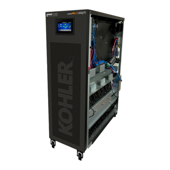
2-2. Rear System View Diagram 1 Rear Panel Diagram 2: Input/Output terminals 1. RS-232 port 11. Line input terminals 2. USB communication port 12. Output terminal 3. Emergency power off connector (EPO 13. Input ground terminal connector) 4. Parallel Share current port 14. - Page 9 1. RS232 Port – Port is used by Maintenance Service engineer to enable updates to internal firmware of the UPS System. Not for Customer Use 2. USB Port – Communication port for Customer to connect monitoring Software directly to local PC, provides Alarms and functional monitoring.
-
Page 10: Single Ups Installation
2-3. Single UPS Installation Installation and wiring must be carried out in accordance with the local installation regulations by trained professionals. Make sure that the mains cable and breakers of the building are rated for the capacity of the UPS to prevent electric shock or risk of fire. - Page 11 Put the terminal block cover back at the rear panel of the UPS. The PowerWAVE 3000/P1 System Can be modified to operate at various configurations of inputs. To change the configuration, insert or remove the provided jumper bars on the terminal rail as detailed below: Warning: ●...
-
Page 12: Ups Installation For Parallel System
2-4. UPS Installation for Parallel System If the UPS is being installed for single operation, you may skip this section. 1) Connect the Parallel (dash lines) & Current Share cables as per the following drawings: 2 X SYSTEM IN PARALLEL 3 X SYSTEMS IN PARALLEL 2) Install and cable the UPS according to the section 2-3. -
Page 13: Operations
Wiring diagram of parallel system 3. Operations 3-1. Initial Operation 1) Before operation, make sure that the two string halves of batteries are connected correctly in order of ”+,GND,-” terminals and the breaker of the battery pack is at “ON” position. 2) Start up UPS system by closing the Input and Bypass breakers, check all settings and configurations before starting up the UPS fully in section 3-4. - Page 14 Menu tree...
- Page 15 3-2-1 Main screen Upon powering on, the LCD will start initialisation after a few seconds as shown below. After initialisation, the main screen will display as shown below. On the bottom, there are five icons to represent five sub-menus: CONTROL, MEASURE, SETTING, INFO, DATALOG. 3-2-2 Control screen Touch the icon to enter control sub-menu.
- Page 16 Enter No Or Back Confirm YES Turn ON /OFF UPS ON/OFF UPS Enter No Or Back Confirm YES Do Battery Test HOME CONTROL BATTERY TEST Enter No Or Back Confirm YES Do MUTE ALL MUTE ALL Enter No Or Back Confirm YES Turn ON/OFF CHARGER ON/OFF CHARGER Screen 1.0 «Control»...
- Page 17 Battery Test Cancel Battery Test Audio mute ➢ It will show “Mute all” if the audio is active. Touch “Yes” to activate mute. If “Mute all” is active, it will show icon on the top left corner of the main screen. Touch “Back” to return to CONTROL screen immediately or “No”...
- Page 18 EXIT PARALLEL? This mode can’t be SETUP!! 3-2-3. Measure screen Touch the icon to enter measure page. Touch the icon to browse information. Touch the icon to return to main screen. Touch the icon to go back to previous menu. Measure screen page 1 LINE VOL: The real time value of L1, L2 and L3 phase voltage, L1-L2, L2-L3, L3-L1 voltage and input ➢...
- Page 19 Measure screen page 2 OUTPUT W: L1 output power in watt. ➢ OUTPUT VA: L1 output power in VA. ➢ OUTPUT W (%): L1 output power watt in percentage. ➢ OUTPUT VA (%): L1 output power VA in percentage. ➢ Total watt and VA: Total output load in watt and VA.
- Page 20 3-2-4. Setting screen This sub-menu is used to set the parameters of UPS. Touch the icon to enter setting menu page. There are 2 options: General and Advanced. Touch the icon to return to main screen. Touch the icon to go back to previous menu. NOTE: Not all settings are available in every operation mode.
- Page 21 Service Contact: Set the name of contact person and the maximum length is 18 characters. ➢ Service Phone: Set the service phone number. Only 0~9, + and – are accepted. The maximum ➢ length is 14 characters. Service Mail: Set the service email accounts up to two and the maximum length is 36 characters. ➢...
- Page 22 ADVANCE Advance Password Page It’s required to enter password (4 digits) to access to the “ADVANCE” page. ADVANCE ➔ ➢ To access to the “Advance➔User” Setting menu page, ENTER Password. If entered password is right, the page will jump to setting screen. If the password is wrong, it will ask to enter again.
- Page 23 ELECTRONIC Electrical Setting Page 1 Output Voltage: Select the output rated voltage. ➢ There are four options, 208V, 220V ,230V and 240V. ◼ Output Frequency: Select output rated frequency. ➢ 50Hz: The output frequency is setting for 50Hz. ◼ 60Hz: The output frequency is setting for 60Hz. ◼...
- Page 24 Electrical Setting Page 2 Bypass at UPS off: Select the bypass status when manually turning off the UPS. This setting is only ➢ available when “Bypass forbid.” is set to “Disable”. Enable: Bypass enabled. When selected, bypass mode is activated. ◼...
- Page 25 BATTERY Battery setting page Battery Warning Voltage: ➢ HIGH: High battery warning voltage. The setting range is 14.0V ~ 15.0V. 14.4V is default setting. ◼ LOW: Low battery warning voltage. The setting range is 10.1V ~ 14.0V. 11.4V is default setting. ◼...
- Page 26 MISCELLANEOUS Miscellaneous setting page Auto Restart: ➢ Enable: After “Enable” is set, once UPS shutdown occurs due to low battery and then utility ◼ restores, the UPS will return to line mode. Disable: After “Disable” is set, once UPS shutdown occurs and the utility restores, the UPS will ◼...
- Page 27 Basic Information MCU Version: MCU version. ➢ DSP Version: DSP version. ➢ Serial NO.: The serial number of UPS. ➢ Manufacturer: The information about manufacturer. ➢ Service Contact: The contact name is set in “Basic Setting”. ➢ Service Phone: The listed numbers are set in “Basic Setting”. ➢...
- Page 28 ECO Mode: Enable/disable ECO function. ➢ Parameter Information Page 1 Parameter Information Line Voltage Range: The acceptable line input voltage range. ➢ Line FRE Range: The acceptable line input frequency range. ➢ Bypass Voltage Range: The acceptable input voltage range for bypass mode. ➢...
-
Page 29: Audible Alarm
3-2-6. Data Log screen Touch the icon to enter date log page. Data log is used to record the warning and fault information of the UPS. The record contains date & time, code, type and description. Touch the icon to page up or down if there are more than one page in the date log. Touch the icon to return to main screen. -
Page 30: Single Ups Operation
3-4. Single UPS Operation 1. Turn on the UPS with utility power (in AC mode) 1) After power supply is connected correctly, set the breaker of the battery pack at “ON” position (this step is only necessary for external battery). Then set the line input breaker, bypass breaker & output breaker to “ON”... - Page 31 voltage drops to the alarm level, the buzzer will beep quickly (once every sec) to remind users that the battery is at low level and the UPS will shut down automatically soon. Users could switch off some non-critical loads to disable the shutdown alarm and prolong the backup time. If there is no more load to be switched off at that time, you have to shut down all loads as soon as possible to protect the devices or save data.
-
Page 32: Parallel Operation
immediately to avoid possible damage to the UPS or equipment. 12. Operation in maintenance bypass mode This operation is only available for professional or qualified technicians. When the UPS needs repair or service and then the load can’t be shut off, the UPS needs to turn to maintenance mode. -
Page 33: Fault Code
3. Remove units from the parallel system Check that Mains and Bypass Supplies are both healthy COMPLETE THE FOLLOWING ON UNIT TO BE REMOVED: Touch “CONTROL” ➔ “Exit Parallel” and select “Yes” to turn of the UPS. If the system has available redundancy the UPS will disconnect its output and the other UPS units will continue to feed the load. -
Page 34: Warning Code
Synchronous trigger signal None PFC IGBT over-current in C phase None failure Parallel communication loss None INV IGBT over-current in A phase None Parallel output current None INV IGBT over-current in B phase None unbalance Battery has reached end of life None INV IGBT over-current in C phase None... -
Page 35: Trouble Shooting
UPS output. circuit status. Other fault codes are shown on LCD display and alarm beeps A UPS internal fault has occurred. Contact Kohler continuously. Charge the batteries for at least 7 hours and then check Batteries are not fully charged. -
Page 36: Storage And Maintenance
5. Storage and Maintenance 5-1. Storage Before storing, charge the UPS for at least 7 hours. Store the UPS covered and upright in a cool, dry location. During storage, recharge the battery in accordance with the following table: Storage Temperature Recharge Frequency Charging Duration -25°C - 40°C... -
Page 37: Specifications
6. Specifications 400V MODEL PW3000/P1 10K PW3000/P1 20K CAPACITY* 10KVA / 10KW 20KVA / 20KW INPUT 110 VAC(Ph-N) ± 3 % at 50% Load Low Line Loss 176 VAC(Ph-N) ± 3 % at 100% Load Voltage Low Line Comeback Low Line Loss Voltage + 10V Range 300 VAC(L-N) ±... -
Page 38: Options
7. Options 7-1 SNMP CARD - OPTIONAL MEDA806 is an SNMP (Simple Network Management Protocol) card for monitoring the PowerWAVE UPS. The SNMP Card provides the ability to monitor the UPS remotely and provide some control. Features: • Provide SNMP MIB to monitor & control UPS •... -
Page 39: Netfeeler Environment Monitoring Card
search. During an abnormal power condition, the SNMP can send the information directly to the user. Provides Shutdown Utilities The computer/server must install the provided shutdown software and the device must be connected to the same network as the SNMP. When the UPS goes into an AC failure condition or Battery Low condition, the software can close all running files of the operating system and shutdown gracefully. -
Page 40: Dry Port Relay Card - Optional
card. When connected to an SNMP Card it can provide environment status feedback (temperature, humidity and water presence) via the internet using a standard browser. 7-3 DRY PORT RELAY CARD - OPTIONAL The dry port relay Card provides contact closures for remote monitoring your UPS. To meet different application requirement, the Relay card is capable of selection the status of the dry-contact signal (active close or active open) by setting jumper. - Page 41 CONTACT DETAILS Kohler Uninterruptible Power Woodgate, Bartley Wood Business Park Hook Hampshire RG27 9XA United Kingdom Telephone: +44 (0) 1256 386 700 Website: www.kohler-ups.co.uk KUP Technical Support: uktechnicalsupport.ups@kohler.com...
Need help?
Do you have a question about the PowerWAVE 3000/P1 and is the answer not in the manual?
Questions and answers