
Related Manuals for Leviton EPCM1-OF3

Summary of Contents for Leviton EPCM1-OF3
- Page 1 Dual Mount Pedestal with Automatic Cable Management Installation Manual Cat. Nos. EPCM1-OF3, EPCM2-OF3, EPCM3-OF3 For use with Cat. Nos. EV320, EV32W, EV48W, and EV48S PK-A3435-10-00-5A...
-
Page 3: Table Of Contents
TABLE OF CONTENTS Warnings ............................4 Installation ............................5 2.1 Making Drill Holes ......................5 2.2 Anchoring ..........................6 2.3 Upper Part Installation ......................7 2.4 Cable Gland Installation ....................9 2.5 Bracket Installation ......................10 2.6 Connector Base Installation ..................11 2.7 Mounting the Charging Station ..................12 2.8 Charger Holder Plate Installation ..................13 2.9 Connecting ........................14 2.10 Positioning the Cable Clamp ..................16... -
Page 4: Warnings
The pedestal must always be fitted with two charging stations! Use of this manual This installation manual is intended for qualified personnel only.The information and instructions in the manual about selecting the location, installation and connection of the charging station must be adhered to. EPCM1-OF3: Quantity EPCM2-OF3: Quantity... -
Page 5: Installation
2 INSTALLATION 2.1 Making Drill Holes 1. Mark the 4 holes on the concrete foundation using the base-plate of the pedestal. Make sure that the connection cable is located precisely underneath the opening in the base-plate. 2. Drill the 4 mounting holes: Diameter: 10 mm. -
Page 6: Anchoring
2 INSTALLATION 2.2 Anchoring 1. Position the pedestal (lower part) directly over the cable outlet. 2. Anchor the pedestal (lower part) to the foundation using 4 sets of M8 100 mm. expansion screws (flat washer, spring washer and bolt were included). 3. -
Page 7: Upper Part Installation
2 INSTALLATION 2.3 Upper Part Installation 1. Connect the junction by 6 sets of M6x20 mm. screws with spring washer and flat washer. 2. Cap the upper part of pedestal with cable management structure. - Page 8 2 INSTALLATION 2.3 Upper Part Installation (Continued) 3. Fix the upper part with 6 sets of M6 20mm screws with spring washer and flat washer.
-
Page 9: Cable Gland Installation
2 INSTALLATION 2.4 Cable Gland Installation 1. Insert the 2 cable glands to the pedestal properly. 2. Fix 2 M8x16mm screws with 5 mm. thread length reserved for charger holder plate. -
Page 10: Bracket Installation
2 INSTALLATION 2.5 Bracket Installation 1. Take off the wall-mounted bracket of 2 chargers, and fix it in the corresponding position on the charger holder plate with 8 of M8x16 mm. screws. -
Page 11: Connector Base Installation
2 INSTALLATION 2.6 Connector Base Installation 1. Use 8 of M5x22 mm. screws to fix the 2 connector bases in the corresponding position of charger holder plate. -
Page 12: Mounting The Charging Station
2 INSTALLATION 2.7 Mounting the Charging Station 1. Mount two (2) charging stations on the charger holder plate using four (4) of M5x12 mm. screws on two sides of the charger (screws from chargers). -
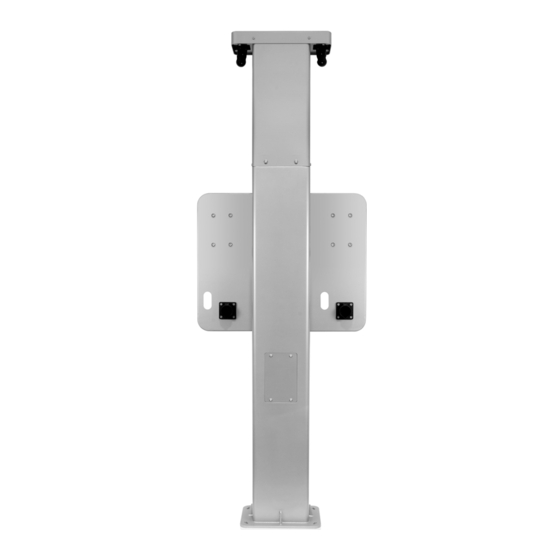
Page 13: Charger Holder Plate Installation
2 INSTALLATION 2.8 Charger Holder Plate Installation 1. Hook the charger holder plate on the screws, and fix with 4 M8x16 mm. screws with spring washer and flat washer. -
Page 14: Connecting
2 INSTALLATION 2.9 Connecting 1. Thread the connection cables from the side to cable gland. - Page 15 2 INSTALLATION 2.9 Connecting (Continued) 1. Perform the electrical connection and commissioning in accordance with the instructions 2. Fix the 4 M6x20 mm. screws of wiring window.
-
Page 16: Positioning The Cable Clamp
2 INSTALLATION 2.10 Positioning the Cable Clamp 1. Pull on the cable of the cable management system to hold the cable clamp in your hand. 2. Remove the two screws as shown below. 3. Determine where to position the charging station cable clamp. Recommendation: The cable portion between the clamp and the charging connector must not touch the ground when the cable management system is completely retracted. -
Page 17: Standard Statements And Warranty
LIMITED 2 YEAR WARRANTY AND EXCLUSIONS Leviton warrants to the original consumer purchaser and not for the benefit of anyone else that this product at the time of its sale by Leviton is free of defects in materials and workmanship under normal and proper use for 2 years from the purchase date.
Need help?
Do you have a question about the EPCM1-OF3 and is the answer not in the manual?
Questions and answers