Table of Contents
Advertisement
Quick Links
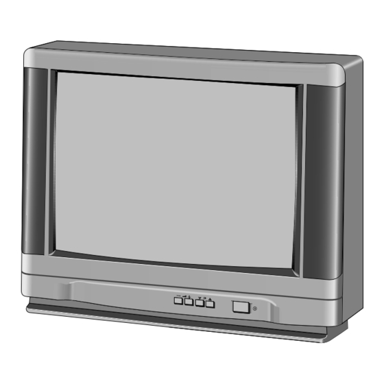
Colour Television
Service Manual
CE21B2-C
(W.Europe)
CE21B2-C
Service Ref. No.
PRODUCT CODE: 111336315
ORIGINAL VERSION: Chassis No. EB4-A
Note
This TV receiver will not work properly in foreign
countries where the television transmission system
and power source differ from the design specifications.
Refer to the specifications for the design specifications
Give complete "SERVICE REF. NO." for parts order or
servicing, it is shown on the rating sheet on the
cabinet back of the TV set.
Specifications
Power source
Television system
Colour system
Receiving channel
Aerial input impedance
AV terminal
21 Pin socket
Sound output(Music)
Picture tube
(Visible picture diagonal)
Dimensions (WxHxD)
Weight
Part No.
SKSM0257
F5JTV
-01
AC 220~240V 50Hz
System B/G
PAL
VHF: E2-E12
CATV: X, Y, Z, S1-S41
UHF: #21~69
75ohm
CENELEC standard
12 watts X2
55cm diagonal, 90 degree
51cm
596 x 466 x 483 mm
21.5 Kg
JUNE 98
CE21B2-C
Advertisement
Table of Contents

Related Manuals for Sanyo CE21B2-C


Summary of Contents for Sanyo CE21B2-C
- Page 1 Colour Television CE21B2-C Service Manual CE21B2-C (W.Europe) CE21B2-C Service Ref. No. PRODUCT CODE: 111336315 ORIGINAL VERSION: Chassis No. EB4-A Note This TV receiver will not work properly in foreign countries where the television transmission system and power source differ from the design specifications.
-
Page 2: Safety Precaution
SAFETY PRECAUTION 1: An isolation transformer should be connected in the 3: When replacing a chassis in the cabinet, always be power line between the receiver and the AC line when certain that all the protective devices are installed a service is performed on the primary of the converter properly, such as, control knobs, adjustment covers or transformer of the set. -
Page 3: Block Diagram
BLOCK DIAGRAM This is a diagram for all models and therefore differs slightly from the actual block diagram. F4MTV... -
Page 4: Circuit Description
CIRCUIT DESCRIPTION 1. POWER SUPPLY control) The chroma signal is divided into R-Y and B-Y The power supply circuit of the EB4-A chassis is chroma signals, demodulated in IC201, and output from composed of a rectifier smoothing circuit, an oscillation pin30 (R-Y) and pin31 (B-Y). -
Page 5: Horizontal Output
6. HORIZONTAL OUTPUT Pin25: Black A horizontal oscillation signal is output from pin37 of Pin26: IREF IC201 and switches the drive transistor Q431. This Pin27: Odd/Even output switching signal is current amplified by the drive Pin28: GND transformer T431 and drives the output transistor Q432. Pin29: - When Q432 becomes ON, an amplifying current flows Pin30: V-deflection stop output... -
Page 6: Service Control Adjustment
SERVICE CONTROL ADJUSTMENT B1 POWER SUPPLY ADJ. AFT ADJ. TU-AGC ADJ. MAIN BOARD HIGH VOLTAGE & H-WIDTH ADJ. FOCUS ADJ. V-CENTRE ADJ. V-SIZE ADJ. H-CENTRE ADJ. GREY SCALE ADJ. SIF BOARD SIF ADJ. CRT BOARD IC3811 IC3801 K38H2 K38H1 AUDIO BOARD IC1251 IC3451 IC3401... - Page 7 B1 POWER SUPPLY ADJUSTMENT HIGH VOLTAGE & WIDTH ADJUSTMENT 1. Set VR641 to be mechanically centre before [HIGH VOLTAGE ADJUSTMENT] pressing the mains ON/OFF switch. 1. Tune the receiver to the circular pattern. 2. Tune the receiver to a PAL circular pattern. 2.
-
Page 8: Circuit Alignment
CIRCUIT ALIGNMENT 10kΩ 0.002µF 75Ω 1kΩ Output probe Input probe VIF alignment SETTING Adjustment Waveform DC 15.5V C644 + By using T141, adjust "P" to AGC voltage (4.3-4.5V) IC201-pin48 be maximum amplitude. Output probe IC201-pin45 (Side b) Input probe IC201-pin7 Marker frequency 38.9MHz Sweep ATT... - Page 9 INITIALISATION (Important Notice) When you replace a memory IC (IC802), it is 2. Select the desired service item by using the Function necessary to initialise the IC as following step. button on the remote control handset. 3. Change the data by using the Level + or - button A.
- Page 10 CABINET PARTS LIST FOR MODELS CE21B2-C Note: Parts order must contain Service Ref. No., Part No., and descriptions. BASS -/-- A•B 1AV0U10B03202 JXRG Item Part No. Description CABINET PARTS 610 273 8834 ASSY,CABINET FR-F5JT 610 272 4370 BUTTON POWER-F4GT 610 261 6798...
-
Page 11: Chassis Electrical Parts List
CHASSIS ELECTRICAL PARTS LIST Product safety should be considered when a component replacement is made in any area of a receiver. Components indicated by a ! mark in this parts list and the circuit diagram show components whose value have special significance to product safety. - Page 12 Ref. No. Part No. Description Part No. Description Ref. No. IC271 409 404 0201 IC U3665M C143 403 027 1211 CERAMIC 5P J IC501 409 183 5008 IC LA7832 C146 403 010 8507 CERAMIC 12P J IC501-1 610 251 5909 V HEAT SINK E7LC C151 403 024 2112 CERAMIC 39P J...
- Page 13 Description Ref. No. Part No. Ref. No. Part No. Description R1911 401 038 6317 MT-GLAZE 470 JA 1/10W R625 401 067 8204 OXIDE-MT 39 JA R1921 401 037 6615 MT-GLAZE 120 JA 1/10W R626 401 016 3344 QARBON 2.2K GA 1/4W R1922 401 038 5013 MT-GLAZE...
- Page 14 Ref. No. Part No. Description Part No. Description Ref. No. R877 401 039 0413 MT-GLAZE 8.2K JA 1/10W D1011 407 063 8319 ZENER DIODE MTZJ11C R878 401 037 7919 MT-GLAZE 1.5K JA 1/10W D1021 407 063 8319 ZENER DIODE MTZJ11C R879 401 037 5618 MT-GLAZE 10K JA 1/10W...
-
Page 15: Assy,Pwb,Sif F2Rt
Description Ref. No. Part No. Ref. No. Part No. Description IC501-1 610 251 8153 VERTICAL RADIATOR-E7PC 645 008 4058 TERMINAL PLUG IC501-2 411 036 3208 SCR PAN+SW+W 3X10 645 008 4058 TERMINAL PLUG IC501-3 411 004 4404 NUT HEX 3 645 008 4058 TERMINAL PLUG J025 401 037 5014 MT-GLAZE... -
Page 16: Assy,Pwb,Audio F2Rt
Ref. No. Part No. Description Part No. Description Ref. No. L3451 401 037 5014 MT-GLAZE 0.000 ZA 1/10W 1AA0B10E230BB ASSY,PWB,AUDIO F2RT MISCELLANEOUS TRANSISTOR J1201 401 037 5014 MT-GLAZE 0.000 ZA 1/10W Q1251 405 109 4407 TR BC848 J1203 401 037 5014 MT-GLAZE 0.000 ZA 1/10W Q1252 405 109 4407 TR BC848... - Page 17 Description Ref. No. Part No. Ref. No. Part No. Description R2653 401 012 7049 CARBON 10K JA 1/4W VARIABLE RESISTOR VR2601 645 003 5722 VR,SEMI,4.7K N VR2602 645 003 5647 VR,SEMI,1K N VR2611 645 003 5722 VR,SEMI,4.7K N VR2612 645 003 5647 VR,SEMI,1K N VR2621 645 003 5722 VR,SEMI,4.7K N COIL...
- Page 18 Ref. No. Part No. Description Part No. Description Ref. No. -19-...
- Page 19 Description Ref. No. Part No. Ref. No. Part No. Description -20-...
- Page 20 2SA564(QA,RA), oppure 2SA1015(O,Y) specified on the part service manual and controls adjusted for normal picture. in posizione "OFF". Il voltaggio puo variare CE21B2-C-01 SERVICE REF.NO. sostituti esclusivamente con quelli indi- a meno che sia specificato altrimenti. be used for components replacement Waveforms were taken by using a wide con l'intensita del segnale.
- Page 21 Main Board /Pannello Principal Circuit side/Lato del Circuito FRONT-IN K12A J10EA020N K12B J10EA R1251 050N 1/10 GJ2.7K SC2-IN R1252 C1251 16EM 1/10 GJ6.8K MONITOR-OUT R1253 1/10 Q1251 GJ82K R1264 2SC2812L6 1/10 :BC848B R1254 GJ82K 1/10 GJ82K Q1252 2SC2812L6 R1263 IC3431 R1257 :BC848B 1/10...
- Page 22 J1EK1745- K1002 :J11B0490N Waveforms on ICs and Transistors ASSY,PWB,CRT F2RC IC201-pin7 IC201-pin15 IC201-pin18 IC201-pin19 IC201-pin20 1AA0B10E24500 <CVBS out> <CVBS in> <B out> <G out> <R out> L2601 Q2601 R2604 L1022 L2C1 2SC2688'1' 2SJ12K Z21B0040N B-OUT 331KN 10 µ s/div. 10 µ s/div. SP901 10 µ...
- Page 23 Main Board /Pannello Principal Component Location/Lato del Componente GENERAL BLOCK DIAGRAM FOR EB4 CHASSIS SW1901 SW1902 SW1904 SW1903 Prog.+ Prog.- Vol.- Vol.+ IC801 21P Scart: AV1 21P Scart: AV2 RC Pre.amp Control Keys Audio I/O Video I/O Video I/O Audio I/O 2: Bright 3: Contranst 4: Colour 5: Sharpness IC801...
Need help?
Do you have a question about the CE21B2-C and is the answer not in the manual?
Questions and answers