Advertisement
Quick Links
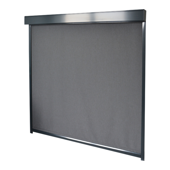
MEASUREMENT AND ASSEMBLY MANUAL
SCREEN ALFA-ZIP, SCREEN ALFA PLUS-ZIP
Taking measurements of the ALFA-ZIP and ALFA PLUS-ZIP screen roller
shutters
Final width B = distance between side pieces.
Final height H = height of the box and guide rail end pieces (thickness of guide rail end pieces =
3 mm) exclusive of the wall/ceiling holder or exclusive of the assembly profile.
Manual validity: 01.09.2022
1
Advertisement

Related Manuals for Isotra ALFA-ZIP


Summary of Contents for Isotra ALFA-ZIP
- Page 1 MEASUREMENT AND ASSEMBLY MANUAL SCREEN ALFA-ZIP, SCREEN ALFA PLUS-ZIP Taking measurements of the ALFA-ZIP and ALFA PLUS-ZIP screen roller shutters Final width B = distance between side pieces. Final height H = height of the box and guide rail end pieces (thickness of guide rail end pieces = 3 mm) exclusive of the wall/ceiling holder or exclusive of the assembly profile.
- Page 2 MEASUREMENT AND ASSEMBLY MANUAL Assembly of the ALFA-ZIP and ALFA PLUS-ZIP screen roller shutters There are several methods of roller blind installation depending on the installation situation. Note: For the self-supporting version of the screen roller shutter assembly, please refer to Variant A, Method 2.
- Page 3 MEASUREMENT AND ASSEMBLY MANUAL Step 3: Centring the fabric in the box 1. Unroll the fabric completely from the roller (the fabric remains slid in the roller groove). Doing this, prevent soiling of the fabric and damage to the lower profile. 2.
- Page 4 MEASUREMENT AND ASSEMBLY MANUAL Guide rails A830, A820: Use predrilled holes in the rails to attach the guide rails A830, A820. Guide rails A838, A828: Step 5: Installing the guide rails Guide rails A839, A829: 1. Attach the holders to the assembly surface. 2.
- Page 5 MEASUREMENT AND ASSEMBLY MANUAL Step 6: Attaching the front cover Reinstall the box front cover. Step 7: Adjusting the motor Set the end positions of the motor depending on the motor type (see manuals for motors). Step 8: Checking the assembly Always make sure the roller blind is properly installed: 1.
- Page 6 MEASUREMENT AND ASSEMBLY MANUAL Method 2. Placing the complete assembly of the box and guide rails in or above the window opening and securing by bolts (used where there is insufficient space for sliding the guide rails on the side piece pin, for example due to the presence of a window sill or for the self-supporting version of the screen roller shutter).
- Page 7 MEASUREMENT AND ASSEMBLY MANUAL Guide rails A830, A820: Use predrilled holes in the rails to attach the guide rails through hole of A830, 820. guide rail Guide rails A838, 828: for holders through hole of guide rail Step 3: Sliding the guide rails on the side piece pins 1.
- Page 8 MEASUREMENT AND ASSEMBLY MANUAL 3. Check whether the fabric rolls up evenly → perform 2–3 control cycles. (CAUTION! End positions of the motor have not been set yet!) End the check by moving the lower rail approx. 15 cm under the box. Step 6: Attaching the box to the wall/ceiling holders, and attaching the guide rails 1.
- Page 9 MEASUREMENT AND ASSEMBLY MANUAL Variant B: Using the assembly profile Step 1: Attaching the profile 1. Place the profile to the assembly surface and indicate the spots according to the predrilled holes. The assembly surface must be perfectly horizontal! 2. Predrill the holes according to the fasteners used and attach the assembly profile.
- Page 10 MEASUREMENT AND ASSEMBLY MANUAL Step 4: Attaching guide rails 1. Slide the guide rails to the side piece pins. 2. Make sure whether the bottom slat end pieces fit properly in the guide rail slots and whether the fabric zipper fits in the plastic insert in the guide rail. 3.
Need help?
Do you have a question about the ALFA-ZIP and is the answer not in the manual?
Questions and answers