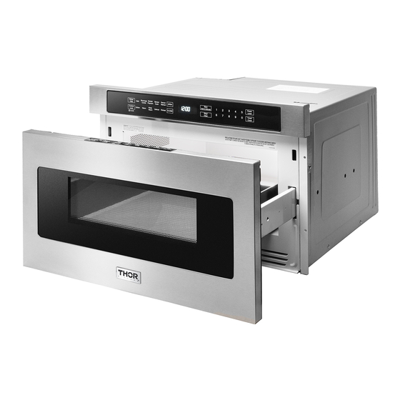
Thor Kitchen TMD2401 Installation Manual
24" drawer microwave
Hide thumbs
Also See for TMD2401:
- Use and care manual (37 pages) ,
- Installation instructions manual (31 pages) ,
- Use & care manual (23 pages)
Table of Contents
Advertisement
Available languages
Available languages
Quick Links
Advertisement
Table of Contents

Subscribe to Our Youtube Channel
Summary of Contents for Thor Kitchen TMD2401
- Page 1 MODEL TMD2401 24" DRAWER MICROWAVE INSTALLATION GUIDE...
-
Page 2: Important Safety Instructions
INSTALLATION GUIDE IMPORTANT SAFETY IMPORTANT–PLEASE READ AND FOLLOW INSTRUCTIONS • Before beginning, read these instructions thoroughly and carefully. • WARNING: If the information in this manual is not followed • Because the kit includes metal parts, caution should be exactly, a fire or electrical shock may result that could cause used in handling and installation to avoid the possibility property damage, personal injury or death. -
Page 3: Grounding Instructions
INSTALLATION GUIDE UNPACKING YOUR DRAWER CLEARANCES AND DIMENSIONS MICROWAVE • Dimensions that are shown in figure 1 must be used. Given dimensions provide minimum clearance. Locate electrical • Remove all packing materials from inside the Drawer Mi- outlet in the shaded area in the upper left-hand corner of crowave. -
Page 4: Drawer Microwave Measurements
INSTALLATION GUIDE DRAWER MICROWAVE MEASUREMENTS FIGURE 2 FIGURE 1 A. 21-5/8" (549.28 mm) B. 4-11/16" (119.06 mm) A. 6" (152.40 mm) C. 1-3/4" (44.45 mm) B. Suggested electrical outlet location* D. 21-7/8" (555.60 mm) C. Anti-Tip block E. 23-7/8" (606.43 mm) D. -
Page 5: Anti-Tip Block
INSTALLATION GUIDE ANTI-TIP BLOCK ELECTRICAL OUTLET The electrical requirements are a 120 volt 60 Hz, AC only, 15 NORMAL INSTALLATION STEPS amp. or more protected electrical supply. It is recommended ANTI-TIP BLOCK INSTALLATION INSTRUCTIONS that a separate circuit serving only this appliance be provided. •... -
Page 6: Drawer Installation
INSTALLATION GUIDE MODEL AND SERIAL NUMBER DRAWER INSTALLATION LOCATION The nameplate includes model number and serial number. Open the Drawer Microwave fully. The label is slightly beyond the back wall of the microwave cavity facing up from the flat surface. CARE, CLEANING AND MAINTENANCE Refer to the User Manual for cleaning instructions. -
Page 7: Instructions De Sûreté Importantes
GUIDE D’INSTALLATION INSTRUCTIONS DE IMPORTANT - S’IL VOUS PLAÎT LIRE ET SUIVRE SÛRETÉ IMPORTANTES • Prière de lire attentivement toutes ces directives avant de commencer. • ADVERTISSEMENT : Si l’on ne suit pas de près les indica- • Le kit comprend des parties métalliques, il faut faire atten- tions dans ce manuel, il y a un risque d’incendie ou de tion lors de la manipulation et de l’installation pour éviter décharge électrique qui pourrait provoquer des dommages... -
Page 8: Instructions Pour La Mise À La Terre
GUIDE D’INSTALLATION DÉBALLAGE DU FOUR DRAWER DÉGAGEMENTS ET DIMENSIONS MICROWAVE • Les dimensions indiquées au Schéma 1 doivent être ob- servées. Ces dimensions offrent un dégagement minimal. • Retirez tout le matériau d’emballage du Drawer Microwave. Repérer la prise électrique dans l’aire ombrée dans le coin N’ENLEVEZ PAS LE COUVERCLE DU GUIDE D’ONDES, qui gauche supérieur de la découpe. - Page 9 GUIDE D’INSTALLATION MESURES POUR LE FOUR DRAWER MICROWAVE SCHÉMA 2 SCHÉMA 1 A. 21-5/8 po (549,28 mm) B. 4-11/16 po (119,06 mm) C. 1-3/4 po (44,45 mm) A. 6 po (152,40 mm) D. 21-7/8 po (555,60 mm) B. Emplacement de la prise électrique* E.
-
Page 10: Bloc Anti-Basculement
GUIDE D’INSTALLATION BLOC ANTI-BASCULEMENT PRISE DE COURANT Le courant alimentation est 120 volts, 60 Hz, CA seulement, 15 ÉTAPES D’INSTA LLATION NORMALE A ou plus et doit être protégé. Il est recommandé d’alimenter DIRECTIVES D’INSTALL ATION DU BLOC cet appareil par un circuit séparé. ANTI-BASCULEMENT Le four est équipé... -
Page 11: Installation Du Tiroir
GUIDE D’INSTALLATION EMPLACEMENT DES NUMÉROS DE INSTALLATION DU TIROIR MODÈLE ET DE SÉRIE La plaque d’identification comprend les numéros de série et de modèle. Ouvrir complètement le four Drawer Microwave. L’étiquette se trouve légèrement au-delà de la paroi arrière de la cavité du four à micro-ondes sur la surface plate. ENTRETIEN, NETTOYAGE ET SERVICE Consulter le mode d’emploi et d’entretien pour les instruc- tions de nettoyage. - Page 12 TINSKB317MRR0 Apr 5, 2021...


Need help?
Do you have a question about the TMD2401 and is the answer not in the manual?
Questions and answers