Table of Contents
Advertisement
Available languages
Available languages
Quick Links
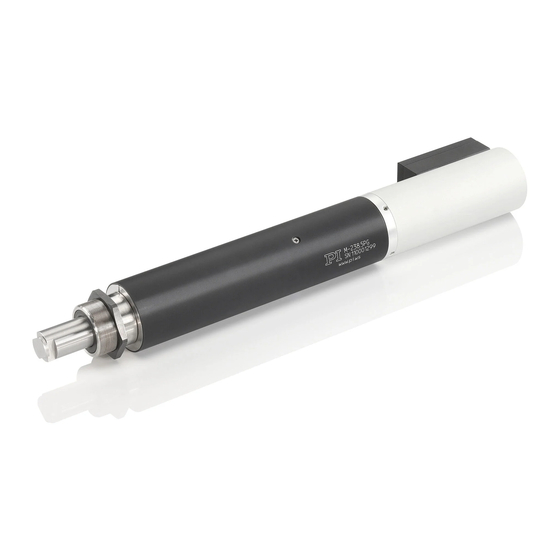
Linear Actuators
MP122EK Short Instructions
M-168 / M-22x / M-23x
Version: 2.1.0
Date: 29.08.2017
User Information
These short instructions contain an overview of the most important safety instructions for linear
actuators with electric motors with the product codes given above (x: arbitrary number).
Downloading and Reading the Manual
The actions during installation, start-up, operation, and maintenance require additional informati-
on from the manuals of the linear actuator and/or the controller used.
Manuals may be titled as follows: „User Manual", „Technical Note".
Downloading manuals from the website:
1. Make a note of the product code on the product (e.g. M-232.17S).
2. Open the website www.pi.ws.
3. For password-protected manuals (CD in the scope of delivery of the product):
a. Insert the CD of the product into the PC.
b. Make a note of the user name and password in the Releasenews file in the \Manuals
folder on the CD.
c. Click Login.
d. Log in with the user name and password.
4. Click Search.
5. Enter the product code up to the period (e. g., M-232) into the search field.
6. Click Start search or press the Enter key.
7. If necessary: Click Load more results at the end of the page.
8. Click on the corresponding product to open the product details page.
9. Scroll down to the Download section.
10. Click the desired manual in the Documentation subsection and save it onto the hard disk of the
PC or onto a data storage medium.
If you cannot find the manual you are looking for, or if you have any questions: Contact our
customer service department via service@pi.de.
Physik Instrumente (PI) GmbH & Co. KG, Auf der Roemerstr. 1, 76228 Karlsruhe, Germany
Phone +49 721 4846-0, Fax +49 721 4846-1019, Email info@pi.ws, www.pi.ws
M O T I O N | P O S I T I O N I N G
MP122EK 2.1.0 08/2017. 0.5
The torque that occurs when the tip is replaced
Safety Instructions
can damage the linear actuator.
Avoid torques to the pusher.
X
A cable break leads to a failure of the linear
Intended Use
actuator.
Install the linear actuator so that the cable
X
The linear actuator is a laboratory device as
is not bent or squeezed too severely during
defined by DIN EN 61010-1. It is intended to be
operation.
used in interior spaces and in an environment
which is free of dirt, oil and lubricants.
Heat produced during operation can affect your
application.
In accordance with its design, the linear actua-
Install the linear actuator so that your
X
tor is intended for positioning and adjusting of
application is not affected by the dissipating
loads at different velocities. The linear actuator
heat.
is not intended for applications in areas in
which a failure would present severe risks to
Start-Up
human beings or the environment.
Operating voltages that are too high or incor-
The intended use of the linear actuator is only
rectly connected can cause damage to the
possible when completely mounted and con-
linear actuator.
nected and only in combination with a suitable
Only use compatible controllers.
X
controller.
Observe the operating voltage range of the
X
The linear actuator may only be installed, ope-
linear actuator (see manual).
rated, maintained and cleaned by authorized
Observe the correct pin assignment (see
X
and appropriately qualified personnel.
manual).
Installation
The linear actuator can carry out an uninten-
tional motion when being connected to the
There is a risk of minor injuries from crushing or
controller.
of property damage between the pusher and a
Before connecting the linear actuator,
X
fixed part or obstacle.
check whether a macro is defined as the
Use protective structures to keep limbs
X
start-up macro in the controller and cancel
away from areas in which they could be
the selection if necessary.
seized by moving parts.
Maintain safety distances according to DIN
Lateral forces that act on the pusher impair the
X
motion of the pusher and increase wear on the
EN ISO 13857.
Mount the linear actuator so that the moti-
drive components.
X
on of the pusher is not hindered by objects
Avoid lateral forces on the pusher of the
X
linear actuator.
in the workspace.
If the linear actuator is vacuum-compatible,
High accelerations can cause damage to or con-
attention must be paid to cleanliness.
siderable wear on the mechanical system.
Only touch the linear actuator with pow-
Stop the motion immediately if a controller
X
X
der-free gloves.
malfunction occurs.
If necessary, wipe the linear actuator clean.
Approach the end of the travel range at low
X
X
velocity.
Overtightening the mounting nut or the moun-
ting screws can damage the mounting shaft and
Unsuitable settings made to the servo-control
parameters can impair the performance of the
hinder the motion of the pusher.
Observe the maximum torque for mounting
linear actuator.
X
(see manual).
Only use the default parameters for the
X
first start-up.
Individually adjust the operating parame-
X
ters (see controller manual).
M O T I O N | P O S I T I O N I N G
MP122EK 2.1.0 08/2017. 0.5
Mounting the Linear Actuator
NOTICE!
Mounting with mounting nut
1. Insert the linear actuator into the mechani-
Damage from incorrect mounting.
cal mounting.
Observe the safety instructions in
X
2. If necessary: Stick a flat washer or spring
the „Installation" section.
washer onto the mounting shaft.
Do not exceed the maximum permis-
3. Clamp the linear actuator with the moun-
X
sible torque of the mounting nut or
ting nut.
the mounting screws (see manual).
4. Check that the linear actuator is affixed
firmly.
Mounting with grub screws
If the linear actuator is to be mounted to the
groove of the mounting shaft, at least one grub
screw must be used.
1. Make at least one threaded hole in the me-
chanical mounting across from the groove
(for dimensions, see manual).
2. Insert the linear actuator into the mechani-
cal mounting.
3. Screw a grub screw into each threaded hole
1
Pusher
so that it engages in the groove.
2
Mechanical mounting
4. Check that the linear actuator is affixed
3
Linear actuator
firmly.
4
Mounting nut
5
Mounting shaft with thread
Changing the Tip
NOTICE!
Torques on the pusher can damage the
drive.
Avoid torques on the pusher.
X
The supplied tips make it possible to realize
different mechanical connections to a load.
1. If necessary (see manual): Use an open-end
wrench to hold the pusher by the wrench
flats.
2. Unscrew the tip to be replaced.
3. Screw in the new tip by hand.
4. If necessary: Remove the open-end wrench
1
Tip with (a) wrench flat
from the pusher.
2
Pusher with (b) wrench flat
5. Check that the tip is affixed firmly.
M O T I O N | P O S I T I O N I N G
Advertisement
Table of Contents

Subscribe to Our Youtube Channel
Related Manuals for Physik Instrumente M-22 Series


Summary of Contents for Physik Instrumente M-22 Series
- Page 1 (see controller manual). 5. Check that the tip is affixed firmly. Physik Instrumente (PI) GmbH & Co. KG, Auf der Roemerstr. 1, 76228 Karlsruhe, Germany Phone +49 721 4846-0, Fax +49 721 4846-1019, Email info@pi.ws, www.pi.ws M O T I O N | P O S I T I O N I N G...
- Page 2 5. Festen Sitz des Kopfstücks überprüfen. Maximales Drehmoment für die Befesti- Physik Instrumente (PI) GmbH & Co. KG, Auf der Römerstr. 1, 76228 Karlsruhe, Deutschland gung beachten (siehe Handbuch). Tel. +49 721 4846-0, Fax +49 721 4846-1019, E-Mail info@pi.de, www.pi.de...
Need help?
Do you have a question about the M-22 Series and is the answer not in the manual?
Questions and answers