Table of Contents
Advertisement
Quick Links
PZ166E
E-625 Piezo Servo Controller
User Manual
Version: 2.0.0
Physik Instrumente (PI) GmbH & Co. KG, Auf der Roemerstrasse 1, 76228 Karlsruhe, Germany
Phone +49 721 4846-0, Fax +49 721 4846-1019, Email info@pi.ws, www.pi.ws
Date: 15.09.2021
This document describes the following products:
E-625.CR
Piezo servo controller, single channel, for
capacitive sensors
E-625.C0
Piezo servo controller, single channel, for
capacitive sensors, only analog control
Advertisement
Table of Contents

Related Manuals for Physik Instrumente E-625.CR


Summary of Contents for Physik Instrumente E-625.CR
- Page 1 E-625.C0 Piezo servo controller, single channel, for capacitive sensors, only analog control Physik Instrumente (PI) GmbH & Co. KG, Auf der Roemerstrasse 1, 76228 Karlsruhe, Germany Phone +49 721 4846-0, Fax +49 721 4846-1019, Email info@pi.ws, www.pi.ws...
- Page 2 © 2021 Physik Instrumente (PI) GmbH & Co. KG, Karlsruhe, Germany. The text, photographs, and drawings in this manual are protected by copyright. Physik Instrumente (PI) GmbH & Co. KG reserves all rights in this respect. The use of any text, images and drawings is permitted only in part and only when indicating the source.
-
Page 3: Table Of Contents
Connect a Positioner to the E-625 ................17 Connecting a Signal Source to the E-625 ..............18 Connecting a Measuring Device to E-625 ..............18 Connecting a PC for the Computer-Controlled Mode (only E-625.CR) ....19 5.8.1 Connecting the E-625.CR to a PC ..............19 5.8.2... - Page 4 Adjusting the Sensor Range ................. 48 8.6.2 Adjusting the Static Sensor Gain for Closed-Loop Operation ...... 51 8.6.3 Adjusting the Sensor Linearization .............. 54 8.6.4 Digital Corrections (only E-625.CR).............. 55 Maintenance Cleaning the E-625 ....................57 Updating Firmware ....................57 Troubleshooting Customer Service Technical Data 12.1 Specifications ......................
- Page 5 12.1.3 Ambient Conditions and Classifications ............67 12.2 Operating Limits ....................... 68 12.3 Dimensions ....................... 69 12.4 Block Diagrams ......................70 12.4.1 E-625.CR Block Diagram ................70 12.4.2 E-625.C0 Block Diagram ................71 12.5 Pin Assignment ......................72 12.5.1 PZT & SENSOR ....................72 12.5.2 Network .......................
-
Page 7: About This Document
1 About this Document About this Document In this Chapter Objective and Target Audience of this User Manual ..............1 Symbols and Typographic Conventions ..................1 Figures ............................2 Other Applicable Documents ......................2 Downloading Manuals ........................3 Objective and Target Audience of this User Manual This user manual contains the information required for using the E-625 as intended. -
Page 8: Figures
1 About this Document Symbol/ Meaning Label Action consisting of several steps with strict sequential order Action consisting of one or more steps without relevant sequential order. Bullet p. 5 Cross-reference to page 5 RS-232 Label on the product indicating an operating element (example: RS-232 interface socket) Warning signs attached to the product that refer to detailed information in this manual. -
Page 9: Downloading Manuals
1 About this Document INFORMATION The E-625.S0 and E-625.SR models for operation with strain gauge sensors are described in a separate manual (PZ167E). Downloading Manuals INFORMATION If a manual is missing or problems occur with downloading: Contact our customer service department (p. 63). Downloading Manuals 1. -
Page 11: Safety
2 Safety Safety In this Chapter Intended Use ..........................5 General Safety Instructions......................5 Organizational Measures ....................... 6 Intended Use The E-625 is a laboratory device according to DIN EN 61010. It is intended to be used in interior spaces and in an environment which is free of dirt, oil and lubricants. Corresponding to its design, the E-625 is intended for driving capacitive loads (e. -
Page 12: Organizational Measures
2 Safety Use the supplied components (power supply, adapter, power cord) to connect the E-625 to the power source. If one of the supplied components for connecting to the power source has to be replaced, use a sufficiently dimensioned component. If a protective earth conductor is not or not properly connected, dangerous touch voltages can occur on the E-625 in the case of malfunction or failure of the system. -
Page 13: Product Description
Features and Applications The E-625 piezo servo controller is a benchtop device that provides closed-loop and open-loop control of the displacement of the positioner. The models E-625.CR and E-625.C0 work with capacitive sensors that measure the position directly and without contact. -
Page 14: Product View
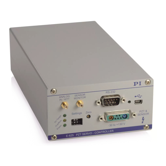
Product View 3.3.1 Front Panel Figure 1: E-625.CR front panel ANALOG IN/WTT SMB socket, coaxial input line grounded on the line conductor. The use depends on the control mode which is set up with the Settings DIP switch block (see below): Version: 2.0.0... - Page 15 D-sub panel plug, (9-pole, male) for the serial connection to the PC. Refer to the user manual for the E-816 computer interface submodule. USB Socket (only E-625.CR) Universal serial bus interface (USB-mini B(m) socket) for the serial connection to the PC. Refer to the user manual for the E-816 computer interface submodule.
- Page 16 Servo mode switched on (closed-loop operation) OFF (up) Servo mode switched off (open-loop operation) E-625.CR only: On the E-816 computer interface submodule, the servo mode can be switched on with the SVO command. Signal on ANALOG IN/WTT used as the trigger for the wave...
-
Page 17: Rear Panel
Rear Panel Figure 2: E-625 rear panel Network D-sub socket, 9-pole, female (p. 72) for the network connection (only E-625.CR; I C-bus), the synchronization of the sensor and the on-target signal from the E-802 servo controller submodule. The on-target signal shows that the distance from the target position is less than ±0.19 % of the travel range. -
Page 18: Scope Of Delivery
PZ300EK Short Instructions for Housed Analog Piezo Electronics PZ150E User manual for the E-802 servo controller submodule Only with E-625.CR: C-815.34 Null modem cable for the connection to the PC 000036360 USB cable (USB-A(m)/USB-Mini-B(m)) for the connection to the PC... -
Page 19: Unpacking
4 Unpacking Unpacking 1. Unpack the E-625 with care. 2. Compare the contents with the scope of delivery according to the contract and the delivery note. 3. Inspect the contents for signs of damage. If any parts are damaged or missing, contact our customer service department (p. -
Page 21: Installation
Connecting a Signal Source to the E-625 ..................18 Connecting the Measurement Device to E-625 ................18 Connect a PC for the Computer-Controlled Mode (only E-625.CR) ..........19 General Notes on Installing Install the E-625 near the power source so that the power plug can be quickly and easily disconnected from the mains. -
Page 22: Connecting The Power Supply To The E-625
5 Installation Requirements You have read and understood the general notes on installation (p. 15). The E-625 is not connected to the power supply. Tools and Accessories Suitable protective earth conductor: Cable cross section ≥ 0.75 mm −... -
Page 23: Connect A Positioner To The E-625
5 Installation Tools and Accessories 15 V wide-range-input power supply included (for line voltages between 100 and 240 volts alternating current voltage at 50 or 60 Hz) Alternative: Sufficiently rated power adapter Barrel-to-Switchcraft adapter for the power supply (K050B0002, included in the scope ... -
Page 24: Connecting A Signal Source To The E-625
5 Installation Connecting a Signal Source to the E-625 Requirements The signal source is switched off or the output is 0 V. Tools and Accessories Suitable signal source: For use as the input voltage for specifying the target value in analog mode: −... -
Page 25: Connecting A Pc For The Computer-Controlled Mode (Only E-625.Cr)
In the computer-controlled mode (p. 32), the target value is given, among other things, by motion commands sent from the PC to the E-625.CR via the RS-232 or USB interface. These commands are processed by the E-816 computer interface submodule on the E-625.CSR. -
Page 26: Interlinking The Controllers
Null modem cable or USB cable (USB-A(m)/USB-mini B(m)) for the connection to the PC (cable included in the scope of delivery). Connecting the E-625.CR to the PC Connect the RS-232 socket using the null modem cable or the USB socket using the USB cable to the PC. - Page 27 5 Installation For the E-625.CR to be interlinked and all other piezo server controllers for capacitive sensors to be added to the network (e.g. E-665.CR), the master/slave setting has been made for the sensor synchronization, see "Synchronizing the Sensors" (p. 41) or the E-665 user manual.
-
Page 29: Startup
6 Startup Startup In this Chapter General Notes on Startup ......................23 Perform System Test ........................24 Adjust the Sensor Zero-Point ....................... 27 General Notes on Startup DANGER Risk of electric shock if the protective earth conductor is not connected! If a protective earth conductor is not or not properly connected, dangerous touch voltages can occur on the E-625 in the case of malfunction or failure of the system. -
Page 30: Perform System Test
6 Startup INFORMATION Thermal instabilities can reduce the performance of the E-625 directly after it is switched on. Switch on the E-625 at least one hour before starting work. If the device is not in use, but should remain switched on to ensure the temperature stability: Make sure that servo mode is switched off (open-loop operation) and the piezo output voltage is set to 0 V:... - Page 31 6 Startup Only if the housing needs to be opened for the adjustment of internal settings: Phillips-head screwdriver, size PH1 − Trimmer adjustment tool − Performing a System Test in Analog Mode 1. Select analog mode and open-loop operation (servo mode OFF) using the Settings DIP switch block: 1: ON (down) −...
- Page 32 6 Startup When the system test in open-loop operation was successful or if you have adapted the notch filter and/or zero point: 5. Switch the servo mode on by moving switch 3 on the Settings DIP switch block to ON (down).
-
Page 33: Adjust The Sensor Zero-Point
6 Startup The E-625 or the positioner was replaced. In this case, the displacement of the axis must first be recalibrated (p. 51). INFORMATION In regular intervals, check the position of the positioner at 0 V input voltage and adjust the sensor zero point if necessary. - Page 34 Appropriate voltmeter (p. 18): necessary in analog mode − − not necessary, but helpful, in computer-controlled mode (only E-625.CR) If the voltmeter is used, an additional SMB/BNC adapter cable is necessary (included in the scope of delivery). Trimmer adjustment tool ...
- Page 35 8. Adjust the Zero potentiometer using the trimmer adjustment tool until the sensor signal is +1 V. Performing the Zero-Point Adjustment in Computer-Controlled Mode (only E-625.CR) 1. Select the computer-controlled mode and the open-loop operation (servo mode OFF) using the Settings DIP switch block: −...
- Page 36 6 Startup INFORMATION To prevent an overflow in open-loop operation: Do not exceed the recommended input voltage range of –2 to +12 V (analog mode). Do not command any piezo voltage outside of the recommended range of –20 to +120 V (computer-controlled mode).
-
Page 37: Operation
7 Operation Operation In this Chapter General Notes on Operation ......................31 Operating Modes ......................... 32 Selecting the Operating Mode ..................... 33 General Notes on Operation DANGER Risk of electric shock if the protective earth conductor is not connected! If a protective earth conductor is not or not properly connected, dangerous touch voltages can occur on the E-625 in the case of malfunction or failure of the system. -
Page 38: Operating Modes
Operating Modes 7.2.1 Control Mode The E-625.CR and the E-625.C0 can be run in analog mode. Alternatively, the E-625.CR can be run in computer-controlled mode. The active control mode determines the applicable control sources for the output voltage. Analog Mode The piezo voltage depends on the input voltage applied to the ANALOG IN/WTT SMB socket. -
Page 39: Servo Mode
7 Operation 7.2.2 Servo Mode The servo mode determines whether the motion is performed in open-loop operation (servo mode OFF) or in closed-loop operation (servo mode ON). The control and servo modes can be combined at will. Closed-Loop Operation Control input signals (input signal on ANALOG IN/WTT or E-816 inputs over commands and wave table output) are interpreted as the target position. -
Page 40: Selecting The Servo Mode
In the default position, the E-802 servo controller submodule is active and the servo mode can be set as follows: Settings of the DIP switch block (E-625.CR and E-625.C0) Move the DIP switch 3 on the front panel of the E-625 to the corresponding position:... -
Page 41: Adjustment Of Internal Settings
8 Adjustment of Internal Settings Adjustment of Internal Settings In this Chapter General Notes on the Adjustment of Settings ................35 Opening the Housing ........................36 Adjustment Elements Inside the Housing ..................37 Synchronizing the Sensors ......................41 Adjusting Notch Filter and P-I Controller ..................43 Calibrating the Displacement of the Positioner ................ -
Page 42: Opening The Housing
8 Adjustment of Internal Settings NOTICE Loss of system settings when internal components are adjusted! When the system settings are changed, the original settings will be lost. Unfavorable settings can lead to oscillation of the positioner, deteriorated settling behavior and reduced positioning accuracy. -
Page 43: Adjustment Elements Inside The Housing
Adjustment Elements Inside the Housing The following figure shows the position of the components and adjustment elements (jumpers, switches) on the main board of the E-625.CR and on the E-802.55 servo controller submodule. The servo controller submodule is inserted vertically on the main board. -
Page 44: Jumper
The servo mode can be controlled with switch 3 on the Settings DIP switch block and (only for E-625.CR) over the E-816 computer interface submodule. The slew rate limiter for the piezo voltage and the notch filter remain active even when servo mode is switched off. - Page 45 8 Adjustment of Internal Settings Jumper X8 The X8 jumper is located on the main board (p. 37). Position Function DC-offset potentiometer is activated. Only activate when a DC-offset potentiometer (not included in the scope of delivery) is connected. DC-offset potentiometer is deactivated. Jumper JP101 to JP106 The jumpers JP101 to JP106 are used to adjust the sensor range.
-
Page 46: Switches
8 Adjustment of Internal Settings Figure 8: Settings for the sensor evaluation range 8.3.2 Switches Switches of the E-802.55 Servo Controller Submodule The mini DIP switches and the S1 switch for the notch filter setting of the E-802.55 servo controller submodule are described in the E-802 servo controller submodule user manual. Master/Slave Switch for the Sensor Synchronization In systems with several capacitive sensors, the master/slave switch makes the master/slave settings. -
Page 47: Potentiometers
The master/slave switch is located on the printed circuit board which is soldered (p. 40) vertically on the main board. Furthermore, for all E-625.CR to be synchronized, wires 7 and 8 as well as a ground wire (1, 2, or 5) of the Network socket must be connected to the corresponding wire. - Page 48 8 Adjustment of Internal Settings INFORMATION If a E-625.CR is to be interlinked with at least one E-665.CR piezo servo controller for capacitive sensors: 1. Configure the E-625.CR as sensor master. 2. Configure all E-665.CR as sensor slaves (see E-665 user manual).
-
Page 49: Adjusting Notch Filter And P-I Controller
8 Adjustment of Internal Settings Adjusting Notch Filter and P-I Controller The E-625 is equipped with a notch filter with which the oscillations at the mechanical resonant frequency can be suppressed in dynamic operation. Adjusting the P-I controller optimizes the system's dynamic properties (overshoot and settling time). - Page 50 8 Adjustment of Internal Settings Tools and Accessories Oscilloscope; recommended: Digital storage oscilloscope (p. 18) Function generator for the output of square and sine wave functions in the range of 1 Hz to 1 kHz 2 SMB/BNC adapter cables (included in the scope of delivery) ...
- Page 51 8 Adjustment of Internal Settings 10. Turn the P4 potentiometer on the E-802.55 servo controller submodule by using the trimmer adjustment tool to optimally adapt the notch filter frequency to the resonant frequency of the positioner. 11. Repeat the last steps until the resonant frequency of the positioner has the best damping.
-
Page 52: Setting The P-I Controller In Analog Mode
8 Adjustment of Internal Settings 8.5.2 Setting the P-I Controller in Analog Mode Requirements You have correctly adjusted the notch filter (p. 43). You have not changed anything on the system setup that was used for the adjustment of the notch filter. -
Page 53: Calibrating The Displacement Of The Positioner
8 Adjustment of Internal Settings Figure 13: Closed-loop operation, P-term set too large (strong overshoot) Figure 14: Closed-loop operation, conservative setting of P-term and I-term, stable system with relatively long settling time Calibrating the Displacement of the Positioner A recalibration of the displacement is only necessary when the positioner (or parts of it) or the E-625 of a calibrated system was replaced. -
Page 54: Adjusting The Sensor Range
In the other control modes, you must expect a deviation of 1 %. With E-625 models that can be operated computer-controlled (E-625.CR), PI does the calibration in the computer-controlled mode by default. - Page 55 − necessary in analog mode − not necessary, but helpful, in computer-controlled mode (only E-625.CR) If the voltmeter is used, an additional SMB/BNC adapter cable is necessary (included in the scope of delivery). High-precision, external measuring device (e.g. interferometer) to measure the ...
- Page 56 If not: Disconnect the E-625 from the power source by removing the power cord of the wide-range-input power supply from the power socket and close the E-625. Adjusting the Sensor Range in Computer-Controlled Mode (only E-625.CR) 1. Select computer-controlled mode and open-loop operation (servo mode OFF) using the...
-
Page 57: Adjusting The Static Sensor Gain For Closed-Loop Operation
8 Adjustment of Internal Settings 5. Establish communication between the PC and the E-625 e.g. with PIMikroMove. 6. Send the SVO A 0 command (A indicates the axis) to ensure that the servo mode is switched off. 7. Increase the piezo voltage using the SVA command in increments of 10 volts from 0 V up to the value where the upper travel range limit for the positioner is reached approximately. - Page 58 E-625. Adjusting the Static Sensor Gain in Computer-Controlled Mode (E-625.CR only) 1. Send the SVO A 1 command (A indicates the axis) to switch on the servo mode.
- Page 59 8 Adjustment of Internal Settings a) Switch the servo mode off immediately. b) Optimize the notch filter frequency and the P-I controller settings in the E-625 (p. 43). c) Make sure that servo mode is switched on. 2. Send the MOV A 0 command. 3.
-
Page 60: Adjusting The Sensor Linearization
8 Adjustment of Internal Settings 8.6.3 Adjusting the Sensor Linearization The sensor linearization should minimize the nonlinear second order contributions to the sensor signal. INFORMATION The sensor linearization can only be optimized for one direction of motion. PI by default makes the optimization for the positive direction of motion, i.e. -
Page 61: Digital Corrections (Only E-625.Cr)
5. Close the E-625. 8.6.4 Digital Corrections (only E-625.CR) In addition to the adjustments described in this user manual, the E-816 computer interface submodule can be used to digitally correct the following values:... -
Page 63: Maintenance
When necessary, clean the surfaces of the E-625's housing using a cloth dampened with a mild cleanser or disinfectant. Updating Firmware The E-625.CR module is equipped with an E-816 computer interface submodule whose firmware can be updated. For updating the firmware of the E-816 computer interface submodule, follow the instructions in the E-816 user manual. -
Page 65: Troubleshooting
E-625.CR only: In the analog mode, motion commands from the computer interface or from running macros, trigger input and wave table output are ignored and can provoke an error message. - Page 66 10 Troubleshooting Problem Possible causes Solution Wrong axis Make sure that the correct axis identifier is used and commanded that the commanded axis belongs to the correct positioner. An axis identifier is even required on systems with only one axis. Incorrect ...
- Page 67 10 Troubleshooting Problem Possible causes Solution The controller was With USB connections, the communication cannot be switched off and maintained after the E-625 has been switched off and on on again or was again or once the E-816 computer interface submodule restarted has been reset.
- Page 68 10 Troubleshooting Problem Possible causes Solution The customer Incorrect Check whether the system works with a terminal software does combination of program. not run with driver routines/Vis If so: the PI drivers Read the information in the corresponding software manual and compare the sample code on the PI software CD with your program code.
-
Page 69: Customer Service
11 Customer Service Customer Service For inquiries and orders, contact your PI sales engineer or send us an email (mailto:service@pi.de). If you have any questions concerning your system, provide the following information: − Product and serial numbers of all products in the system −... -
Page 71: Technical Data
Pin Assignment ..........................72 Subject to change. The latest product specifications are available on the webpage of the product at www.pi.ws (https://www.pi.ws). 12.1 Specifications 12.1.1 Data Table E-625.CR, E-625.C0 Function Piezo amplifier / servo controller Channels Sensor E-625.CR, E-625.C0 Controller type... -
Page 72: Maximum Ratings
12 Technical Data Interfaces and operation E-625.CR, E-625.C0 Communication interfaces* USB, RS-232 (D-sub 9 (m)), 24-bit A/D and 20-bit D/A Piezo connection D-sub special Sensor connector D-sub special Analog input socket Sensor monitor socket Controller network* up to 12 channels... -
Page 73: Ambient Conditions And Classifications
12 Technical Data 12.1.3 Ambient Conditions and Classifications The following ambient conditions and classifications for the E-625 must be observed: Area of application For indoor use only Maximum altitude 2000 m Air pressure 1100 hPa to 0.1 hPa Relative humidity Highest relative humidity 80 % for temperatures up to 31 °C Decreasing linearly to 50 % relative air humidity at 40 °C... -
Page 74: Operating Limits
12 Technical Data 12.2 Operating Limits The following diagram shows the operating limits in open-loop operation for various piezo loads. The curve values are capacitance values in μF. Figure 15: Operating limits Version: 2.0.0 PZ166E E-625 Piezo Servo Controller... -
Page 75: Dimensions
12 Technical Data 12.3 Dimensions Figure 16: E-625 dimensions in mm E-625 Piezo Servo Controller PZ166E Version: 2.0.0... -
Page 76: Block Diagrams
12 Technical Data 12.4 Block Diagrams 12.4.1 E-625.CR Block Diagram Figure 17: E-625.CR block diagram "S1 sw. 4", "S1 sw. 1", "S1 sw. 2" and "S1 sw. 3" refer to the switches 4, 1, 2 and 3 on the Settings DIP switch block on the E-625 front panel. -
Page 77: E-625.C0 Block Diagram
12 Technical Data 12.4.2 E-625.C0 Block Diagram Figure 18: E-625.C0 block diagram "S1 sw.4", "S1 sw. 1", "S1 sw. 2" and "S1 sw. 3" refer to the switches 4, 1, 2 and 3 on the Settings DIP switch block on the E-625 front panel. The pin numbers 2a to 32c refer to an internal 32 pin connection and are only used for informational purposes. -
Page 78: Pin Assignment
12 Technical Data 12.5 Pin Assignment 12.5.1 PZT & SENSOR Special Sub-D Mix 7W2 socket for the transmission of the piezo voltage and the sensor signals. Function PZT output (–30 to+130 V) Sensor probe ID chip (not supported) AGND target and ID ground PZT ground (connected with housing) Not connected Sensor target... -
Page 79: E-625.Cn Network Cable
12 Technical Data 12.5.3 E-625.CN Network Cable Figure 19: Pin assignment of E-625.CN network cable 12.5.4 Power Supply Connector Switchcraft panel plug, 3-pole, male Function 12 to 30 VDC (15 V recommended), stabilized Not connected E-625 Piezo Servo Controller PZ166E Version: 2.0.0... -
Page 81: Old Equipment Disposal
Dispose of your old equipment according to international, national, and local rules and regulations. In order to fulfil its responsibility as the product manufacturer, Physik Instrumente (PI) GmbH & Co. KG undertakes environmentally correct disposal of all old PI equipment made available on the market after 13 August 2005 without charge. -
Page 83: Appendix
14 Appendix Appendix In this Chapter Lifetime of PICMA® Actuators ..................... 77 European Declarations of Conformity ..................81 14.1 Lifetime of PICMA® Actuators The lifetime of a PICMA® piezo actuator can be influenced by the following factors: Applied voltage Temperature ... - Page 84 14 Appendix Figure 21: Dependency of the mean time between failure (MTTF) of a PICMA® actuator on the ambient temperature Figure 22: Dependency of the mean time between failure (MTTF) of a PICMA® actuator on the relative humidity Version: 2.0.0 PZ166E E-625 Piezo Servo Controller...
- Page 85 14 Appendix The calculated lifetime in hours results from the product of the values for the individual contributions: MTTF = A × A × A : Contribution of the applied voltage : Contribution of the ambient temperature : Contribution of the relative humidity The contribution of the applied voltage is especially important for applications.
-
Page 87: European Declarations Of Conformity
14 Appendix 14.2 European Declarations of Conformity For the E-625, declarations of conformity were issued according to the following European statutory requirements: Low Voltage Directive EMC Directive RoHS Directive The standards applied for certifying conformity are listed below. Safety (Low Voltage Directive): EN IEC 61010-1 EMC: EN 61326-1 RoHS: EN IEC 63000 E-625 Piezo Servo Controller...
Need help?
Do you have a question about the E-625.CR and is the answer not in the manual?
Questions and answers