Table of Contents
Advertisement
MS173E User Manual
C-863 Mercury™
DC Motor Controller
Release: 1.2.7
Date: 2008-04-24
This document describes the
following product:
C-863
DC Motor Controller, Single-Axis, Networkable
© Physik Instrumente (PI) GmbH & Co. KG
Auf der Roemerstr. 1 ⋅ 76228 Karlsruhe, Germany
Tel. +49 721 4846-0 ⋅ Fax: +49 721 4846-299
info@pi.ws ⋅ www.pi.ws
Advertisement
Table of Contents

Related Manuals for Physik Instrumente C-863 Mercury


Summary of Contents for Physik Instrumente C-863 Mercury
- Page 1 This document describes the following product: C-863 DC Motor Controller, Single-Axis, Networkable © Physik Instrumente (PI) GmbH & Co. KG Auf der Roemerstr. 1 ⋅ 76228 Karlsruhe, Germany Tel. +49 721 4846-0 ⋅ Fax: +49 721 4846-299 info@pi.ws ⋅ www.pi.ws...
- Page 2 Physik Instrumente (PI) GmbH & Co. KG is the owner of the following company names and ® trademarks: PI , PIMikroMove™, Mercury™, Mercury™ Step The following designations are protected company names or registered trademarks of third parties: Windows, LabVIEW Copyright 2008 by Physik Instrumente (PI) GmbH & Co. KG, Karlsruhe, Germany.
- Page 3 D e c l a r a t i o n o f C o n f o r m i t y according to ISO / IEC Guide 22 and EN 45014 Manufacturer: Physik Instrumente (PI) GmbH & Co. KG Manufacturer´s Auf der Römerstrasse 1...
- Page 4 This document is available as PDF file on the product CD. Updated releases are available for download from www.pi.ws or by email: contact your Physik Instrumente Sales Engineer or write info@pi.ws. Conventions The notes and symbols used in this manual have the following meanings:...
-
Page 5: Table Of Contents
Introduction Introduction Overview..................3 Prescribed Use ................4 Safety Precautions ..............5 Unpacking.................. 7 Accessories ................7 Software Interfaces..............8 1.6.1 Native Command Set ..............8 1.6.2 GCS Command Set..............8 1.6.3 Available Software..............8 Quick Start Front and Rear Panel Elements ..........11 Connecting Mercurys™... - Page 6 Introduction Troubleshooting Technical Data Specifications ................33 Dimensions................34 Connector Pinouts ..............35 7.3.1 Motor-Connector............... 35 7.3.2 I/O Connector ................36 7.3.3 Joystick Connector ..............36 7.3.4 Joystick Y-cable................ 37 7.3.5 RS-232 Connectors ..............37 7.3.6 USB Connector................. 38 7.3.7 Power Connector & Grounding Screw ........39 Disposal www.pi.ws C-863 MS173E Release 1.2.7...
-
Page 7: Introduction
The networking feature allows the user to start out with one Mercury™ controller and add more units later for multiaxis setups. The C-863 Mercury™ DC motor controller shares its native programming language with its predecessor, the C-862 and with the Mercury™ Step stepper motor controller. -
Page 8: Prescribed Use
PI controllers such as piezo drivers and multi-axis servo-controllers with minimal programming effort. Prescribed Use Based on its design and realization, the C-863 Mercury™ Controller is intended to drive PI stages with DC motor or voice coil drives. Observe the safety precautions given in this User Manual. -
Page 9: Safety Precautions
Introduction Max. relative humidity 80% for temperatures up to 31°C, decreasing linearly to 50% relative humidity at 40°C Line voltage fluctuations not greater than ±10% of the line voltage Transient overvoltages as typical for public power supply Note: The nominal level of the transient overvoltage is the standing surge voltage according to the overvoltage category II (IEC 60364-4-443). - Page 10 Introduction CAUTION Never connect a stepper motor to a C-863 DC motor controller. Irreparable damage could result. CAUTION Do not enable a joystick axis here when no joystick is connected to the controller hardware. Otherwise the corresponding controller axis may start moving and could damage your application setup.
-
Page 11: Unpacking
Introduction Unpacking Unpack the C-863 Mercury™ controller with care. Compare the contents against the items covered by the order and against the packing list. In C-863.10, the following components are included: Mercury™ Controller (C-863.10) Wide-range 15 V power supply (C-890.PS) Power-supply line-voltage cable RS-232 null-modem cable for PC connection (C-815.34, 3 m) -
Page 12: Software Interfaces
Introduction Software Interfaces The C-863 Mercury™ shares many features and commands with other Mercury™ class controllers from PI. It is possible to use either the Mercury™ native ASCII command set or the PI General Command Set (GCS) to operate Mercury™ Class controllers. - Page 13 Introduction separate manuals. Updated releases are available on www.pi.ws or via email: contact your PI Sales Engineer or write info@pi.ws. PITerminal is a Windows program which can be used as a simple terminal with almost all PI controllers. It supports both direct and via-GCS-DLL connection to Mercury™...
- Page 14 Introduction GCS DLL (Windows DLL Library): The Mercury™ General Command Set Dynamic Link Library (Mercury™ GCS DLL) is an intermediate layer providing easy access to the controller from Windows programs. The use of the DLL and the functions it contains is described in a separate manual (MS154E).
-
Page 15: Quick Start
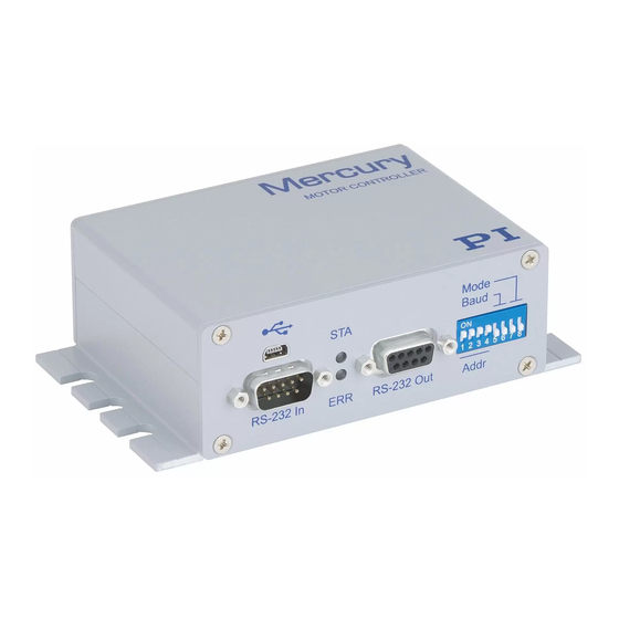
RS-232 or USB port on a host computer and are connecting a motorized axis to each controller. Be sure to refer to the User Manuals of all other hardware in the system. Front and Rear Panel Elements Fig. 2: Front view of C-863 Mercury™ Front Labeling Element Type... -
Page 16: Connecting Mercurys™ With The Host Pc
If using a non-standard power supply for the Mercury™ and a motor that connects to these lines (i.e. without separate PWM amplifier), make sure the motor’s operating voltage will not be exceeded. Fig. 3: Rear view of C-863 Mercury™ Rear Labeling... -
Page 17: Rs-232 From Host
Quick Start Use either the RS-232 or the USB interface to connect the controller or controller network to the host PC. Interconnect any additional Mercury™ Class controllers being networked with straight-through RS-232 cables chaining from the RS-232 OUT to the RS-232 IN connectors of each in turn. NOTE Windows NT does not have USB support as standard. -
Page 18: Usb Driver
Quick Start This section describes the procedures necessary to install the various programs. 2.3.1 USB Driver If using the USB interface, the USB driver must be installed as described in the section on connecting the USB interface, Section 2.2.2 above. 2.3.2 GCS Software If you wish to use any of the GCS-based software, the Windows Setup installation... -
Page 19: Starting Operation
Quick Start Starting Operation Make sure each controller is set to a suitable device address. The factory default setting of the address DIP switches is all ON, corresponding to device number 1. Each Mercury™ Class controller in a network must be set to a unique address. - Page 20 Quick Start Start the PI host software you wish to use and set it up for the stage(s) connected to your system. The sample screen shots that follow are from PIMikroMove™, though MMCRun can be used instead; more details on the host software operation are given in the respective software manual.
- Page 21 Quick Start Fig. 5: PIMikroMove™ Start up controller: Step 2: select stage and be sure to click Assign before moving to Step 3 with OK Fig. 6: PIMikroMove™ Start up controller, Step 3: Reference the axis After communication has been established, make sure the motion parameters of each axis are set as required for the mechanics.
- Page 22 Quick Start stage parameter values directly. Appropriate starting values are given in the User manual for the stage. Make sure that the controller knows the absolute position of each axis (i.e. that the axis is referenced). If the software did not prompt for referencing (as in Fig.
-
Page 23: System Description
System Description System Description Control of Multiple Axes C-863 and C-862 Mercury™ controllers can be networked with each other or with C-663 Mercury™ Step stepper motor controllers. Up to 16 controllers can be connected to one RS-232 or USB port. The controllers interconnect with an RS-232 bus architecture. -
Page 24: Power-Up Settings
System Description Power-up Settings The C-863 Mercury™ has the following power-up settings: Setting Power-up value Unit Velocity: 45000 counts/s Acceleration: 400000 counts/s P-term: I-term: D-term: I-Limit: 2000 Limit logic level active high Limit enable limits enabled Brake mode brake on Values can be set at any time by command (e.g. -
Page 25: Limit Signals
System Description daisy-chained from RS-232 OUT to RS-232 IN in this manner . Note that unique controller addresses must be set for network operation, but they do not need to be in any particular order. Fig. 7: C-862.CN Mercury™ Class network cable, length 28 cm, other lengths available on request Power (15 to 30 VDC, 15 V recommended) must be supplied at the power in connector. -
Page 26: Reference Signal
Input/Output Lines C-863 Mercury™ controllers offer 4 digital outputs and 4 inputs for either digital or analog (8-bit resolution) use (see p. 36 for pinout of the I/O socket). A set of commands is available to handle these I/O lines (for descriptions see the respective native or GCS Commands manual). -
Page 27: Dip Switch Settings
System Description DIP Switch Settings Switch 1 to 4: Address / device number (16 possible combinations) Switch 5 and 6: Baud rate Switch 7 Limit switch mode Fig. 8: slider up ON Switch 8 Firmware update mode slider down Factory settings are shown in bold. Dev. -
Page 28: Firmware Update
System Description Firmware Update It is possible to update the Mercury™ firmware over the RS-232 PC interface. The controller architecture with separate boot loader and firmware proper is designed to prevent aborted updates from locking up the device. However, it is still recommended that firmware updates be executed with care and not be made the subject of experimentation. - Page 29 System Description NOTE MMC_Update cannot determine the exact type of controller connected. If Mercury™ Step firmware is loaded in a Mercury™ DC motor version or vice- versa, the unit will not start. In such a case, try rerunning MMC_update with the correct firmware type.
- Page 30 System Description NOTE Using the Stop Update button is not recommended. 11. Click Start Update once and once only. The four bars above the status line will provide progress information, and log messages will appear in the field above them (see table below). If an error occurs, power cycle the controller and repeat steps 9-11 12.
-
Page 31: Manual Control
Otherwise the corresponding controller axis may start moving and could damage your application setup. C-863 Mercury™ motor controllers offer convenient manual motion control by using analog joysticks (order number C-819.20). With joystick mode enabled, any number of current-production Mercury™ class controllers can be joystick-operated, even while another Mercury™... -
Page 32: Pushbuttons
Manual Control Joystick control accessories: C-819.20 Analog Joystick C-819.20Y Cable to connect one Joystick to two current-production Mercury™ Class controllers. Each controller sees only one axis and the states of that axis’ buttons Fig. 11: C-819.20 Joystick for Mercury™ Controllers Pushbuttons The C-170.PB pushbutton box connects to the Mercury™... -
Page 33: Macros
Macros Macros The Mercury™ controller macro feature allows defining command sequences and storing them permanently in non-volatile memory in the controller. Each defined macro can be executed later by command. A Start-up macro can be defined that will be executed automatically every time the controller is started, making possible customized stand-alone operation without a host computer. -
Page 34: Troubleshooting
Troubleshooting Troubleshooting NOTE The controller must be power-cycled to read in new DIP switch settings. Power-cycling will return internal parameters to their power-up values. Problem (1): When the Mercury™ is powered up, both front-panel LEDs stay dark (normally upper LED lights green). Solution: Make sure that: Switch #8 on the front panel is in lower position (firmware... - Page 35 Troubleshooting The device does not respond to your own terminal program. Problem (4): Solution: Make sure that: Communication can be established with PI software You have sent the proper address selection code or that there is an SC command in the autostart macro with the proper unit address (see Native Commands manual for explanation) Baud rate settings on controller and host match Problem (5):...
- Page 36 Troubleshooting The controller does not seem to react properly to limit signals from the Problem (7) stage. Solutions: Verify that the “limit-switch-polarity” and “stage-has-limit- switches” axis-parameters (depends on stage type) are set properly (in native command set, commands: Lx, in GCS SPA) Non-PI stage limit signal not compatible with Mercury™...
-
Page 37: Technical Data
Technical Data Technical Data Specifications C-863.10 Function DC motor servo-controller, 1 channel Drive type DC motor or voice coil Channels Motion and control Controller type P-I-D servo-controller Trajectory profile modes Trapezoidal, point-to-point Encoder input A/B quadrature TTL level, differential as per RS-422; 20 Stall detection Automatic motor stop when programmable position error is exceeded... -
Page 38: Dimensions
Technical Data Manual control (optional) Joystick, Y-cable for 2D-motion; pushbutton box Miscellaneous Operating voltage 15 to 30 VDC, 15 V recommended, if higher voltage used, connected motor must be compatible Current draw 80 mA + motor current (3 A max.) Operating temperature range 5 to 50°C Mass... -
Page 39: Connector Pinouts
Technical Data Connector Pinouts 7.3.1 Motor-Connector Fig. 14: Sub-D 15(f) motor connector Function Programmable output (brake control) (0 or + 5V) Motor – (differential, power PWM*) Motor + (differential, power PWM*) Power GND PWM magnitude (TTL-level output) PWM sign (motion direction, TTL-level output) +5 V (output) Negative limit signal (input) Positive limit signal (input) -
Page 40: I/O Connector
Technical Data 7.3.2 I/O Connector Pin Signal Function input Input 1 (analog 0 to +5V / digital, TTL) input Input 2 (analog 0 to +5V / digital, TTL) input Input 3 (analog 0 to +5V / digital, TTL) input Input 4 (analog 0 to +5V / digital, TTL) output Output 1 (digital, TTL) output... -
Page 41: Joystick Y-Cable
Technical Data 7.3.4 Joystick Y-cable The joystick Y-cable (C-819.20Y) maps the second joystick-axis (Y) position and button signals to the joystick inputs for the second controller as shown below: Joystick Signal Controller 1 (X) Controller 2 (Y) Button 2: 0 or 3.3 V Vcc (3.3 V supply input) 3.3 V output n.c. -
Page 42: Usb Connector
Technical Data RS-232 IN and RS-232 OUT Connectors Pin on all Signal name on all Mercury™ Mercury™ Connectors Connectors* Signal direction Function n.c. 2 RxD* PC to controller** Commands 3 TxD* Controller** to PC Reports (responses) n.c. 5 GND n.c. n.c. -
Page 43: Power Connector & Grounding Screw
Technical Data 7.3.7 Power Connector & Grounding Screw Power and protective ground connections are on the rear panel: Connector Direction Function Barrel connector: Center input 15 to 30 V DC Barrel connector: Outside input Power GND Grounding screw Protective ground (lower left) CAUTION—Maintain Compliance Because the unit is not grounded over the power supply, a grounding screw is... -
Page 44: Disposal
EU mixed with other wastes. To meet the manufacturer’s product responsibility with regard to this product, Physik Instrumente (PI) GmbH & Co. KG will ensure environmentally correct disposal of old PI equipment that was first put into circulation after 13 August 2005, free of charge.
Need help?
Do you have a question about the C-863 Mercury and is the answer not in the manual?
Questions and answers