Advertisement
Quick Links
Installation
NOTICE: Accumulation of condensate in the wall sleeve. Interruption of the thermal insulation composite system.
Damage to exterior wall/masonry and the building structure.
► Create the wall opening with a slope of 1 – 2° to the exterior wall. Attach the wall sleeve with a slope of 1 – 2° to the exterior wall.
► Replace the wall construction as far as the wall sleeve. Observe the necessary barrier levels.
NOTICE: Penetration of condensation water and/or algae accumulation around the weather protection grille
may cause discolouration of the facade.
► Before installing the exterior closure, carry out all sealing measures (sealing tapes, outdoor sealing compound).
► In vulnerable areas, apply a biocidal/water repellent treatment to the plaster surface around the weather protection hood before installing. (Consult your
planner!)
Tape measure, angle grinder, spirit level, 2K fitting foam, cutter, marker pen, drill with 6 mm bit, Screws (8x, in scope of delivery)
Step 1: Install the wall sleeve
1
2
115
Ø
X
3
4
5
1 – 2°
24 h
Step 2: Install the weather protection grille
1
2
3
Step 3: Install the ALD insert
1
2
3
4
5
1
Drill a wall opening, Ø 115 mm, with a slope of 1 – 2° to the exterior wall.
X
2
Determine the exact wall thickness X.
Adjust the wall sleeve to the determined wall thickness (X).
3
Insert the wall sleeve into the wall opening from the outside. Fix the wall
sleeve inside and outside with a slope of 1 – 2° to the exterior wall.
4
Fill the gap between the wall sleeve and the masonry on the exterior and
interior wall with non-pressing fitting foam.
5
Cut the fitting foam and protruding mounting wedges flush with the exterior
and interior wall.
1
Insert the weather protection grille into the wall sleeve from the outside.
Level it using a spirit level. Mark the 4 corner drill holes.
Remove the casing from the wall sleeve.
Drill the 4 corner drill holes with Ø 6 mm, min. 50 mm deep.
Insert the rawl plugs.
2
On the exterior, generously apply the permanently elastic outdoor sealing
compound to the connection piece and the base plate.
3
Screw the prepared casing to the exterior wall with 4 screws.
1
Insert the ALD insert into the wall sleeve from the interior.
Level it using a spirit level. Mark the 4 corner drill holes.
Remove the ALD insert from the wall sleeve.
Drill the 4 corner drill holes with Ø 6 mm, min. 50 mm deep.
2
Push the sealing ring flush with the casing onto the ALD insert.
Insert the ALD insert into the wall sleeve.
3
Screw the casing to the interior wall.
4
Attach the top of the inner cover to the locking hook on the casing.
5
Fold the lower area onto the casing.
Set the desired intensity of the air flow (see: Setting the flow rate).
Operation
Setting the flow rate
The air volume is regulated via the lower part of the inner cover. There is
a mechanism for changing the opening angle. Set the opening angle as
follows to increase/decrease the flow rate:
2
Level 1: Min
Level 3: Max
Adjust the lower locking hook to the required level by lifting it out slightly
in the lower part of the inner cover (Flow rates: see Specifications/
Pressure/flow rate curve)
Cleaning and maintenance
The exterior-wall air outlet aV100 ALD is virtually maintenance-free. In order
to maintain full functionality and performance and to ensure good air quality,
the ventilation unit must be checked every six months for contamination of
the wall sleeve and filter. Adjust the cleaning interval as needed and/or to
the air quality.
The included dust filters are reusable and can be washed under warm run-
ning water. Replace excessively contaminated or defective filters.
Remove the inner cover for cleaning: Carefully unscrew the inner cover from
the locking hooks on the bottom and top of the casing. Then pull the filter
cartridge out of the wall sleeve.
Remove the contaminated filter from the filter cartridge and clean it under
warm running water.
Wait until the filter is completely dry.
Insert the clean filter into the filter car-
tridge.
Wipe the interior of the wall sleeve with a
damp cloth. Slide the filter cartridge into
the wall sleeve as far as the stop.
Reattach the inner cover to the casing (see reverse: Install the ALD insert,
step 3 onwards) and set the required air flow intensity (see reverse: Setting
the flow rate).
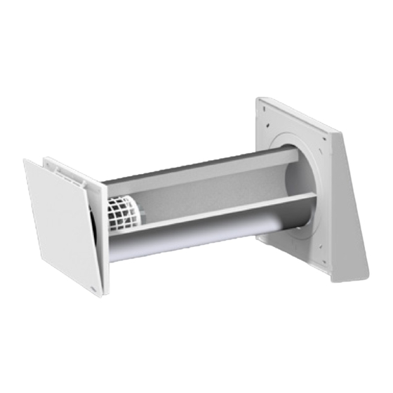
aV100 ALD
Instructions for use
Read before use and keep with product.
The following components are included in the delivery:
• aV100 ALD, item number 1002-0029
weather protection grille (white), sealing ring (2x), Wall sleeve,
ALD insert including inner cover, dust filter and back-draught shutter
accessories
The following
are available from inVENTer GmbH:
• Pollen filter aV100 ALD (2x), item number 1004-0163
• Dust filter aV100 ALD (2x), item number 1004-0164
• Flimmer filter aV100 ALD (1x), item number 1004-0165
• Sound insulation insert aV100, item number 1004-0166
• Wind protection insert WSE R-D100, item number 1004-0173
inVENTer GmbH
Ortsstraße 4a
D-07751 Löberschütz
Version dated 07/2017
+49 36427 / 211-0
Item number 5012-0007
+49 36427 / 211-113
info@inventer.de
Subject to modifications.
We accept no liability for printing errors.
www.inventer.eu
© inVENTer GmbH 2017
Advertisement

Related Manuals for inVENTer aV100 ALD


Summary of Contents for inVENTer aV100 ALD
- Page 1 Step 2: Install the weather protection grille Insert the weather protection grille into the wall sleeve from the outside. The exterior-wall air outlet aV100 ALD is virtually maintenance-free. In order Level it using a spirit level. Mark the 4 corner drill holes.
- Page 2 Supply air area association. Installation may only be carried out by qualified personnel. The aV100 ALD is designed to supply outdoor air in residential areas or similar. In particular, it must not be used in environments that contain a high concen-tration of oil or grease, areas in which extreme dust loads...
Need help?
Do you have a question about the aV100 ALD and is the answer not in the manual?
Questions and answers