
Related Manuals for SOMAG NSM 400


Summary of Contents for SOMAG NSM 400
- Page 1 NSM 400 User Manual Document Number: 112304-901-08/03 SOMAG AG Jena Am Zementwerk 8 mail: info@somag-ag.de 07745 Jena | Germany web: www.somag-ag.de...
- Page 2 Updated: Conversion to new corporate design February 02, 2022 Section 3 ‘Specifications’ / constant lateral accelerations addition Section 4.1 ‘Mechanical Installation’ / device orientation added Section 6.2 ‘Transport and Storage’ / packing dimensions added 112304-901-08/03 NSM 400 2 / 26...
-
Page 3: Table Of Contents
4.1.3 Continuous Torque Estimation ......................14 4.1.4 Dimensions of Fastening Holes / Footprint ..................16 4.1.5 Installation / Installing the NSM 400 ....................16 4.1.6 Main Dimensions / Mounting the Payload ..................16 Electrical Installation ..........................18 4.2.1 General Advice ........................... 18 4.2.2... - Page 4 Mount Communication Protocol ......................23 Maintenance, Transport and Storage ......................24 Maintenance ............................24 Transport and Storage ........................... 24 Troubleshooting .............................. 25 Firmware Update ............................ 25 Reshipment ............................. 25 Powerless Top Surface Movement ....................... 26 112304-901-08/03 NSM 400 4 / 26...
-
Page 5: Safety
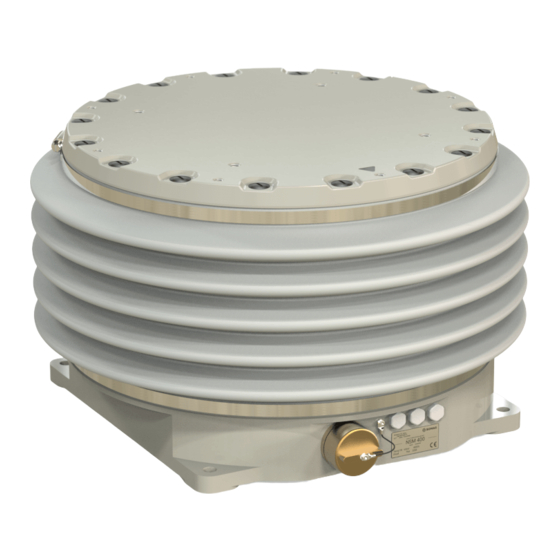
Handling instruction / DO NOT use marked place to handle the device 1.2 Proper Usage The NSM 400 (Nautical Gyro Stabilization Mount) is designed to automatically stabilize cameras, scanners, LIDARs and all other surveying equipment in two rotational axes. The device is used to compensate random vehicle movements. -
Page 6: Watertightness Disclaimer
SOMAG AG Jena reserves the right to perform a cause analysis of devices damaged by water ingress to de- termine whether the defect is covered by the warranty. In case of damage to the bellow or connector ports, do NOT expose the Stabilization Mount to water, dust or any other harsh environment to prevent critical damage. -
Page 7: Environmental- And Application Conditions
1.6 Falling or ejected objects Regularly check the tightening of the Stabilization Mount and payload fas- teners. 112304-901-08/03 NSM 400 7 / 26... -
Page 8: Safety Area
Mount. It is the user’s responsibility to do a risk analysis to define the right area size according to the circumstances as shown in Figure 1and in accordance with the used payload. Distance between Mount pivot and top mounting plate; compare Figure 5 112304-901-08/03 NSM 400 8 / 26... -
Page 9: General Safety Tips
• DO NOT lift the NSM 400 by the areas marked by the red crosses. You will likely squeeze your hands if you use these positions to lift and carry the device. Furthermore, it is possible to damage the shell of the unit. -
Page 10: Standard Scope Of Delivery
MAIN/AUX/ETH, straight plug straight plug 110003-001-06/XX 112304-901-08/XX 110080-901-08/XX USB flash drive with software NSM 400 Manual SOMAG Mount Control App – SOMAG Mount Control App Manual 112300-385-02/XX 112304-400-03/XX Bag with Handling Details and Por- Transportation and Storage Box tage Sensors... - Page 11 Please make sure that the items according to your quote, purchase order and delivery are included in your package and contact the manufacturer (SOMAG AG Jena) if an item is missing! 112304-901-08/03...
-
Page 12: Specifications
Maximum duration 90 s at 55 °C surrounding temperature / longer if temperature inside the unit is < 55 °C Horizontal payload CoG offsets are not considered; without wind force and other possible external forces 112304-901-08/03 NSM 400 12 / 26... -
Page 13: Installation
4.1.3. Data example (blue marked): The NSM 400 will work properly with a payload weight of 250 kg, a payload Center of Gravity of approx. 450 mm above the mounting surface (see Figure 5) and maximum lateral accelerations (caused by the vessel on which the Mount is installed) of 0.5 g. -
Page 14: Continuous Torque Estimation
Figure 3: NSM 400 mass – center of gravity – lateral acceleration correlation 4.1.3 Continuous Torque Estimation The continuous torque, which needs to be smaller or equal to the continuous torque shown in chapter 3, can be estimated using the following formulas: Formula Symb. - Page 15 The Mount can only work properly when the continuous torque (M ), which is caused by the cont payload and its environmental conditions, is smaller than the continuous torque limit of the Mount shown in chapter 3. 112304-901-08/03 NSM 400 15 / 26...
-
Page 16: Dimensions Of Fastening Holes / Footprint
Position the device straight over the installation holes. • Install the NSM 400 with four screws. A torque of 30 Nm is required to secure the device safely. 4.1.6 Main Dimensions / Mounting the Payload Figure 5 illustrates the main dimensions of the device, the payload mounting holes and the pivot. 8x M8 / 12 mm and 4x M10 / 15 mm deep threaded holes are provided for installation purposes. - Page 17 Figure 5: NSM 400 payload mounting holes, main dimensions, cog and pivot • It is always desired to move the center of gravity of the payload to the middle of the usable diameter. This ensures the best dynamic behavior and stabilization performance of the Mount and avoids an unnecessary increase in power consumption.
-
Page 18: Electrical Installation
4.2.2 Cabling of the NSM 400 Figure 6: Cabling of the NSM 400 A – Grounding Use the M5 / 6 mm deep threaded hole to ground the NSM 400. Replace the protective nylon screw with a metal screw! •... -
Page 19: Power J1 Cable
The basic interface cable is used to bridge the distance between the Mount and the interface cable J2. Cable lengths up to 30 m are possible. Figure 7: Wiring scheme interface J2 cable (left) and interface J2 basic cable (right) 112304-901-08/03 NSM 400 19 / 26... -
Page 20: Interface J2 Cable
MAIN (RS-422) AUX J2 (RS-422) male, 4-40 UNC thread Function Function RxD- RxD- RxD+ RxD+ TxD+ TxD+ TxD- TxD- n.c. signal-GND 6 … 9 n.c. n.c. housing ground ground Pins must not be connected. 112304-901-08/03 NSM 400 20 / 26... -
Page 21: Interface J3 Cable
4.3 SOMAG Mount Control App Installation Information regarding the installation of the SOMAG Mount Control App can be found in the following docu- ment: ‘110080-901-08/XX SOMAG Mount Control App Manual’. Pins must not be connected. 112304-901-08/03 NSM 400... -
Page 22: Getting Started
The device runs the electronic test phase (ETP) to check proper functionality of all sensors and electronic components. When the MTP, RTP and ETP are completed, the NSM 400 turns into its preset default mode (can be set up with the SOMAG Mount Control App / see chapter 5.1). -
Page 23: Manual Operation (Man Mode)
Check that the ‘MAN’ Mode is selected (‘MAN’ Mode button shines yellow) in the SOMAG Mount Control App (see chapter 5.1) and use the sliders to move roll and pitch (yaw axis is not enabled on the NSM 400). Under certain movement conditions (strong turbulence, harsh environmental conditions), for troubleshooting purposes or for checking the safety area of the payload it can be necessary to control the Mount manually with the SOMAG Mount Control App (see chapter 5.1). -
Page 24: Maintenance, Transport And Storage
The NSM 400 should be returned to the manufacturer for maintenance every two years. The requirement for service is also signaled in the SOMAG Mount Control App (see chapter 5.1). Should a malfunction of the Mount occur, please contact SOMAG AG Jena to solve the problem as quickly as possible. -
Page 25: Troubleshooting
Troubleshooting • It is strongly recommended to contact the manufacturer (SOMAG AG Jena) immediately if a problem occurs. Any repairs not authorized by the manufacturer will void the warranty. 7.1 Firmware Update If you need to change or update the firmware version, please contact your local support or the manufacturer, SOMAG AG Jena. -
Page 26: Powerless Top Surface Movement
Make sure to turn back the grey rotary knob to its start position (Figure 9/ Step 1) to enable automatic functionality of the Mount. • Ensure to refit the bronze cover to the Mount, as otherwise watertightness cannot be guaran- teed. 112304-901-08/03 NSM 400 26 / 26...
Need help?
Do you have a question about the NSM 400 and is the answer not in the manual?
Questions and answers