Advertisement
Quick Links
Advertisement

Subscribe to Our Youtube Channel
Related Manuals for Noblewell NWCT1B


Summary of Contents for Noblewell NWCT1B
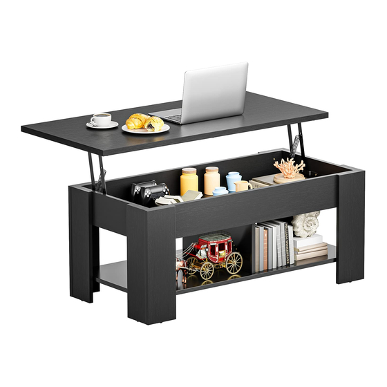
- Page 1 Lift Top Coffee Table Instruction Manual...
- Page 2 Supplied Parts and Hardware ① ⑨ ⑨ ⑧ ⑩ ④ ⑦ ② ⑥ ② ⑤ ⑦ ③ ⑧ ⑪ ⑫ ⑩ ⑨ C*24 D*24 M6x12mm M3.5x14mm M3.5x25mm M3.5x35mm H*22 I*16 J*14 - 1 -...
- Page 3 Tools Needed (Not lncluded) Phillips Screwdriver Rubber Mallet CAM LOCK SYSTEM OPERATION 1. Screw the cam bolt [C] into the threaded insert on the panel. 2. Connect both panels together making sure cam bolt [C] goes into the pre-drilled large hole on the end of panel for cam lock [D]. 3.
- Page 4 STEP 1 ② Phillips Screwdriver (Not lncluded) ④ ② ③ Note: Keep the grooves on the panels ② ③ ④ are at the same level. ②*1 ③*1 ④*1 C*2 J*4 - 3 -...
- Page 5 STEP 2 Phillips Screwdriver (Not lncluded) ⑤ ⑪ Note: Make sure the four big holes point to the bottom in this step. ⑤*1 ⑪*1 J*3 - 4 -...
- Page 6 STEP 3 Phillips Screwdriver (Not lncluded) ⑪ ⑤ - 5 -...
- Page 7 STEP 4 ⑥ ⑥*1 - 6 -...
- Page 8 STEP 5 ② ② ②*1 C*2 D*2 J*4 - 7 -...
- Page 9 STEP 6 Phillips Screwdriver (Not lncluded) ⑪ ⑫ Note: Keep these big holes points ⑫*1 J*3 to outwards in this step. - 8 -...
- Page 10 STEP 7 ⑨ ⑩ ⑨ ⑩ Phillips Screwdriver (Not lncluded) Rubber Mallet (Not lncluded) Make sure these holes ⑨*2 ⑩*2 C*10 D*6 F*4 face down in this step. - 9 -...
- Page 11 STEP 8 ⑦ ⑧ ⑦ ⑧ Phillips Screwdriver (Not lncluded) Rubber Mallet (Not lncluded) Make sure these holes ⑦*2 ⑧*2 C*10 D*6 F*4 face down in this step. - 10 -...
- Page 12 STEP 9 ⑨ Phillips Screwdriver (Not lncluded) ⑩ ⑦ ⑧ ⑫ ⑧ ⑦ ⑩ ⑨ - 11 -...
- Page 13 STEP 10 Phillips Screwdriver (Not lncluded) I*16 - 12 -...
- Page 14 STEP 11 Phillips Screwdriver (Not lncluded) ① ①*1 E*6 H*6 - 13 -...
- Page 15 STEP 12 Phillips Note: Keep the spring points to inwards and the two vertical Screwdriver frames are close to the front side of the top panel ① in this (Not lncluded) step. Vertical Frame Front ① ① A*1 B*1 G*4 H*4 - 14 -...
- Page 16 STEP 13 Phillips Screwdriver (Not lncluded) You may need assistance with H*12 this step. - 15 -...
Need help?
Do you have a question about the NWCT1B and is the answer not in the manual?
Questions and answers