Table of Contents
Advertisement
Quick Links
Advertisement
Table of Contents

Related Manuals for eGPS Solutions 20T

Summary of Contents for eGPS Solutions 20T
- Page 1 20T GNSS Receiver Quick Start Guide...
- Page 2 Copyright Copyright 2021 eGPS Solutions, Inc. | All rights reserved. Trademarks All product and brand names mentioned in this publication are trademarks of their respective holders. Safety Warnings The Global Positioning System (GPS) is operated by the U.S. Government, which is solely responsible for the accuracy and maintenance of the GPS network.
-
Page 3: Table Of Contents
1.1.2. Regulations and Safety......1.1.3. Use and Care........1.2. Technical Support..........1.3. Disclaimer............1.4. Your Comments..........2. Getting Started with the eGPS 20T 2.1. About the Receiver..........2.2. Parts of the Receiver 2.2.1. Front Panel........... 2.2.2. Lower Housing........2.2.3. Receiver Ports........ - Page 4 3. Communication Ports Definition 3.1. eGPS 20T Receiver I/O Port (7-Pin Lemo Port) Definition..........4. Contact Information............. 5. Warranty Terms............6. 20T Specifications............
-
Page 5: Introduction
1. Introduction The eGPS 20T GNSS Receiver Quick Start Guide describes how to set up and use the eGPS 20T GNSS receiver. “The receiver” refers to the eGPS 20T GNSS receiver unless otherwise stated. Even if you have used other Global Navigation Satellite... -
Page 6: Use And Care
1.2. Technical Support If you have a problem and cannot find the information you need in this manual or on the eGPS Solutions website www.egps.net, you can contact our technical support team at (770) 695-3361. 1.3. Disclaimer... -
Page 7: Your Comments
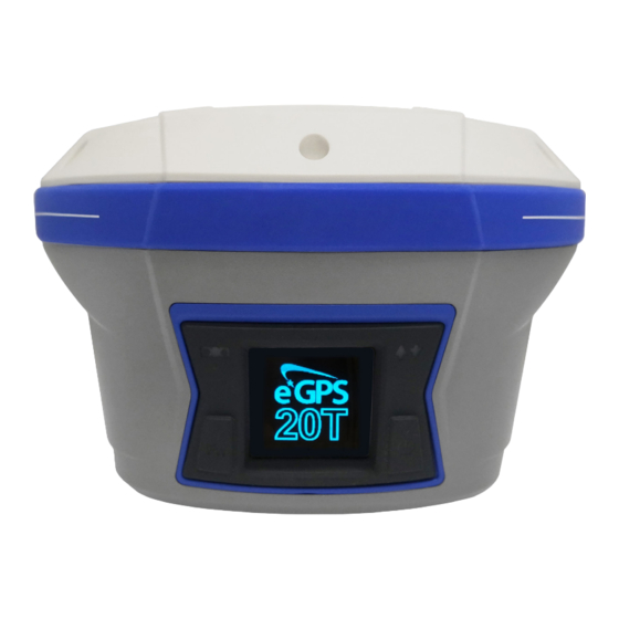
2. Getting Started with the eGPS 20T 2.1. About the Receiver The eGPS 20T GNSS receiver incorporates a GNSS engine, GNSS antenna, internal radio, 4G cellular modem, Bluetooth, WiFi and dual batteries in a ruggedized and miniature unit. Either unit may be a base, rover, or used without other devices for static collection. -
Page 8: Parts Of The Receiver
2.2. Parts of the Receiver The operating controls are all located on the front panel. Battery compartment and SIM card slot are located on the back. Serial ports and connectors are located on the bottom of the unit. 2.2.1. Front Panel The following figure shows a front view of the receiver. - Page 9 Indicator Color Description LED/ Button Correction Green • Indicated whether the receiver is transmitting/receiving differential data. • The green LED flashes once per second when: a) As a Base Station: successfully transmitting differential data. b) As a Rover Station: successfully receiving differential data from Base Station.
- Page 10 Power Button Function Button Function Button Power Button Name Color Description Function Yellow • Move to the next line of the menus Button or options. • Move to next character of the value that you want to change. • Cancel the change you make on a function.
-
Page 11: Lower Housing
2.2.2. Lower Housing The lower housing contains one SIM card slot, two battery compartments, one TNC radio antenna connector, two communication and power ports, one 5/8-11 threaded insert, and two nameplates. -
Page 12: Receiver Ports
2.2.3. Receiver Ports Port Name Description I/O Port This port is a 7-pin LEMO connector that supports RS-232 communications and external power input. Users can use the HCE320 Type-C Cable supplied with the system to realize RS-232 communications between the receiver and computer or controller. -
Page 13: Batteries And Power
Do not charge or use the battery if it appears to be damaged or leaking. • Charge the lithium-ion battery only in an eGPS 20T charger that is specified to charge it. Be sure to follow all instructions that are provided with the battery charger. -
Page 14: Battery Safety
2.3.1.2. Battery Safety WARNING - Do not damage the rechargeable lithium-ion batteries. A damaged battery can cause an explosion or fire and can result in personal injury and/or property damage. To prevent injury or damage: • Do not use or charge the battery if it appears to be damaged. -
Page 15: External Power Supply
2.3.2. External Power Supply Two methods are available for providing external power to the receiver. Use the included GPS to USB PC Data Cable with Power Adapter and either the wall charging adapter or the optional 12 volt battery cable. In the office: The Power Adapter is connected with AC power of 100 - 240 V and the output port of the Power Adapter... -
Page 16: Inserting Batteries And Sim Card
2.4. Inserting Battery and SIM Card Push down on the button on the battery cover to open the cover. Align the connectors of the batteries with the connections on the receiver. Insert the battery into the battery compartment until it is locked by the battery bail. Snap the battery cover back into place when finished. -
Page 17: Product With Accessories
2.5. Product with Accessories Item Picture eGPS 20T GNSS Receiver UHF Bar Antenna (450-470 MHz) P/N: 2004 020 011 HCE320 USB Type-C Lithium Batteries P/N: 2004 050 017 Battery Charger P/N: 2004 050 030 C300 Auxiliary H.I. Tool Rover Hard Case... -
Page 18: Connecting To An Office Computer
2.6. Connecting to an Office Computer The receiver can be connected to an office computer for serial data transfer or settings via a HCE320 USB Type-C. Before you connect to the office computer, ensure that the receiver is powered on by the internal battery or external power. -
Page 19: X-Pad Project Setup
2.7. X-PAD Project Setup 1. To start a project, go to the ‘Job’ tab, and select ‘New/Open Job’. 2. Clicking on the icon indicated allows you to choose your job interface style (Gallery, List, Map, or Calendar). Explore these options, and select the one that best suits your approach. - Page 20 3. Give your project a name. The other settings are explored in more depth elsewhere. Hit ‘Accept’. 4. Select ‘Coord’ to review coordinate system selection. You will notice it is greyed out. We will see how to change the system later.
- Page 21 5. ‘Position’ (job location) can be hand entered, address based, picked from screen, or determined using the handheld collector’s location services/internal GPS (tap ‘Update Position’). You need internet access for maps to appear. 6. You can include a picture here. It will show up as a thumbnail if you select ‘Gallery’...
- Page 22 7. Use the left arrow at the bottom of the screen to get back to here. Then select ‘Coordinate System’. 8. Select the coordinate system that is appropriate for your project. For this example, we used SPC GA-West. More details on coordinate system selection and use are available in the user’s...
- Page 23 9. Pick ‘Tools’ below, and see the pop-up menu on the next screen. 10. Select ‘Load predefined system’. The other options are suitable for differing survey styles or to save settings for future use/archiving.
- Page 24 11. Pick the ‘down arrow’ to review your options. You will need to scroll through the list when it appears. 12. Select the coordinate system grouping that is appropriate for your project. We used ‘US-NAD83’ for the example. Scroll through the options, and select the appropriate system/region for your work.
- Page 25 13. Select the coordinate system that is appropriate for your project. For this example, we used SPC GA-West. Hit ‘Accept’. Hit ‘GNSS localization’. 14. Pick the arrow to the right at the bottom of the screen to select a Geoid. We used 2018 for this example.
- Page 26 15. Select the appropriate Geoid. We used 2018B, US, for this example. Hit ‘Accept’. 16. Use the left arrow at the bottom of the screen to get back to here. Click ‘Settings’.
- Page 27 17. From this menu, you can reach X-Pad settings for Instruments, Jobs, etc. You will use it for a variety of settings and preferences. The following screenshots will provide settings for illustration. You need to tailor these to suit your practices and the specifics of your site/project.
- Page 28 19. Click ‘Decimals’ under ‘Job settings’ to get here. Continue through the choices under ‘Job settings’ to set your preferences. Note: You should review ‘Coordinates’ under ‘Job settings’. X-Pad comes default to Easting, Northing. 20. Once you set a job up, consider saving it ‘with a name’...
-
Page 29: X-Pad Network Rover
2.8. X-PAD Network Rover 1. You can find this screen by selecting the settings icon at the bottom of the screen. Pick ‘GNSS & Total stations’. 2. Select ‘Add’ below to open dialogue for new instrument. You will use this in the future to add other instruments. - Page 30 3. Click ‘GNSS Receiver’ to open dialogue for GNSS setup. 4. Give the profile a name. If you are using a variety of sensors and/or configurations, consider developing a clear nomenclature scheme.
- Page 31 5. Select CHC. 6. Change settings to those shown here. Click ‘Next’ when done.
- Page 32 7. Find and/or select the appropriate Bluetooth connection (The Bluetooth ID is the serial number located on the bottom of the device.) If you do not see it listed, select ‘Add device’ below and search for it. Click ‘Next’ when done. 8.
- Page 33 9. Select the appropriate RTK correction stream. Since we are using a ‘network base’, select ‘Internal GPRS’ or ‘External GPRS’. For the example, we are using the data collector’s internet connection and will select ‘External’. Click ‘Next’ when done. 10. Use this screen to enter your RTK stream information.
- Page 34 11. You can adjust your satellite cutoff angle here. Move sliders to use GLONASS, BEIDOU, and GALILEO. Adjust update frequency as appropriate for your task. Click ‘Next’ when done. 12. Leave antenna model set to ‘Integrated’. Height is the rod height. Additional offset will not be used here but can be used if unit is mounted above a...
- Page 35 13. Select ‘Yes’ here. 14. Good news. You are ready to work.
- Page 36 15. Make sure the profile you set is current. To change profiles, you can use the right arrow and select ‘Current’. From here you can start surveying.
-
Page 37: X-Pad Radio Base
2.9. X-PAD Radio Base 1. You can find this screen by selecting the settings icon at the bottom of the screen. Pick ‘GNSS & Total stations’. 2. Select ‘Add’ below to open dialogue for new instrument. You will use this in the future to add other instruments. - Page 38 3. Click ‘GNSS Receiver’ to open dialogue for GNSS setup. 4. Name profile as described in previous sections. Change to ‘GNSS Base’. Change Brand to ‘CHC’. Click ‘Next’.
- Page 39 5. Find and/or select the appropriate Bluetooth connection (The Bluetooth ID is the serial number located on the bottom of the device.) If you do not see it listed, select ‘Add device’ below and search for it. Continue as described in previous sections.
- Page 40 7. Select the appropriate RTK correction stream. Since we are using a ‘radio (UHF) base’, select ‘Internal radio’ for standard radio configuration. Click ‘Next’ when done. 8. The first time you configure the radio, you may need to populate the channels.
- Page 41 9. An example configuration is shown. The base and rover must use the same Channel frequency, Protocol, Spacing, FEC setting, and Format. If base ID is selected, it must be set to match in Rover setup. Note: FCC licensing required for GNSS radios.
- Page 42 11. Leave antenna model set to ‘Integrated’. Height is the rod height. Additional offset will not be used here but can be used if unit is mounted above a prism, etc. Click ‘Accept’. 12. Select ‘Yes’ here. When you prepare to start surveying using a base-rover configuration, it is advisable to confirm that the Base...
-
Page 43: X-Pad Radio Rover
2.10. X-PAD Radio Rover 1. You can find this screen by selecting the settings icon at the bottom of the screen. Pick ‘GNSS & Total stations’. 2. Select ‘Add’ at the bottom of the screen. Click ‘GNSS Receiver’ to open dialogue for GNSS setup. - Page 44 3. Name profile as described in previous sections. 4. Name profile as described in previous sections. Change to ‘GNSS Rover’. Change Brand to ‘CHC’. Click ‘Next’.
- Page 45 5. Find and/or select the appropriate Bluetooth connection (The Bluetooth ID is the serial number located on the bottom of the device). If you do not see it listed, select ‘Add device’ below and search for it. Continue as described in previous sections.
- Page 46 7. The first time you configure the radio, you may need to populate the channels. If ‘No frequencies’ is indicated on the first line, click ‘Tools’ below and ‘Load configuration from receiver’. See ‘Radio Base’ section for more details. The base and rover must use the same Channel frequency, Protocol, Spacing, FEC setting, and...
- Page 47 9. Leave antenna model set to ‘Integrated’. Height is the rod height. Additional offset will not be used here but can be used if unit is mounted above a prism, etc. Click ‘Accept’. 10. Select ‘Yes’ here.
- Page 48 11. GNSS will take a moment to configure. 12. The configuration you just prepared should have a check indicating it is the current configuration. If it is not, you can pick the arrow (>) to the right of the configuration and select ‘Current’.
-
Page 49: X-Pad Static
2.11. X-PAD Static 1. Click ‘Settings’, then ‘GNSS & Total stations’, ‘Add’ (bottom of screen), then ‘GNSS Receiver’ to get here. Once here, name profile and set as indicated. We will make a profile for Static data collection. Click ‘Next’ when done. 2. - Page 50 3. Select ‘None’. No RTK corrections required for Static data collection. Click ‘Next’ when done. 4. You can adjust your satellite cutoff angle here. Move sliders to use GLONASS, BEIDOU, and GALILEO. Adjust update frequency as appropriate for your task. Click ‘Next’...
- Page 51 5. Leave antenna model set to ‘Integrated’. Height is the rod height. Additional offset will not be used here but can be used if unit is mounted above a prism, etc. Click ‘Accept’. 6. Good news. You are ready to collect Static data.
- Page 52 7. To start a static session, go to ‘Survey’, and select ‘Static survey’. 8. Wait for connection.
- Page 53 9. Set: Log File name. Occupation time (You can choose preselected times or ‘Manual’). Logging rate. File type (see popup to the right). You can select Rinex if you are submitting to OPUS, etc. Antenna height. Hit ‘Next’.
- Page 54 10. You can enter point number and code here. From here, click ‘Start occupation’, and follow prompts from software.
-
Page 55: Communication Ports Definition
3. Communication Ports Definition 3.1. eGPS 20T Receiver I/O Port (7-Pin Lemo Port) Definition Function Ground ( - ) Ground ( - ) RS232-TX (Output) Not Used RS232-RX (Input) -
Page 56: Contact Information
The purchaser’s sole remedy shall be replacement as provided above. In no event shall eGPS Solutions be liable for any damages or other claim including any claim for lost profits, lost savings or other incidental or consequential damages arising out of the use of, or inability to use, the product. -
Page 57: T Specifications
6. 20T Specifications GNSS Specifications 336 channels with simultaneously tracked satellite signals L1C, L1 C/A, L2E, L2C, L5 GLONASS L1 C/A, L2 C/A, L3 CDMA BeiDou B1, B2 , B3 Galileo E1, E5A, E5B, E5AltBOC, E6 SBAS L1 C/A, L5 (L-Band capable) - Page 58 Communication Network Modem Integrated 4G modem LTE (FDD): B1, B2, B3, B4, B5, B7, B8, B20 | DC-HSPA+/HSPA+/HSPA/UMTS: B1, B2, B5, B8 | EDGE/GPRS/GSM 850/900/1800/1900 MHz WiFi 802.11 b/g/n, access point mode Bluetooth v4.1 Ports 1 x 7-pin LEMO port (external power and RS-232) 1 x USB Type-C port (data download, firmware update) 1 x UHF antenna port (TNC female)
- Page 59 Performance Specifications Real-Time Kinematics (RTK) Horizontal 8 mm + 1 ppm RMS Vertical 15 mm + 1 ppm RMS Initialization Time < 10 s Initialization Reliability > 99.9% Post-Processing Kinematics (PPK) Horizontal 2.5 mm + 1 ppm RMS Vertical 5 mm + 1 ppm RMS Post-Processing Static Horizontal 2.5 mm + 0.5 ppm RMS...
Need help?
Do you have a question about the 20T and is the answer not in the manual?
Questions and answers