
Related Manuals for AUTO-BLiP Lotus

Summary of Contents for AUTO-BLiP Lotus
- Page 1 AUTO-BLiP INTELLIGENT DOWNSHIFTS www.AUTO-BLiP.com User Manual Lotus Version 1.2 Copyright © 2012 Tractive Technology, LLC. All rights reserved. Page 1...
- Page 2 Do Not mount the AUTO-BLiP where it can obstruct the view of the driver Do Not mount the AUTO-BLiP in a manner that could cause it to be propelled through the vehicle during an accident causing injury, such as over or near an air bag ...
- Page 3 Note: When performing this installation, make sure the wire harness is securely routed away from any moving parts! If posible, secure the Auto-Blip harness to the car manufacturer's harness for added safety. Note: Soldering the Auto-Blip harness wires (6) to the respective car wires provides for the best results.
- Page 4 1. Using a pair of pliers, securely attach supplied wire t-taps to all the specified wires shown in Figures 2, 3, 4 and 5. 2. Connect the AUTO-BLiP’s spade connectors to each of the specified t-tap as shown in Figures 2, 3, 4 and 5. Lotus wire color coding...
- Page 5 Figure 1 (Clutch pedal position sensor connector) Copyright © 2012 Tractive Technology, LLC. All rights reserved. Page 5...
- Page 6 AUTO-BLiP AUTO-BLiP YELLOW BLACK wire wire connection connection Clutch pedal position sensor Figure 2 (Clutch pedal sensor wiring diagram) Copyright © 2012 Tractive Technology, LLC. All rights reserved. Page 6...
- Page 7 Brake pedal AUTO-BLiP BLUE switch wire connection Figure 3 (Brake pedal sensor wiring diagram) Copyright © 2012 Tractive Technology, LLC. All rights reserved. Page 7...
- Page 8 Accelerator pedal position sensor AUTO-BLiP RED wire connection AUTO-BLiP GREEN wire connection Figure 4 (Accelerator pedal sensor wiring diagram) Copyright © 2012 Tractive Technology, LLC. All rights reserved. Page 8...
- Page 9 ALTERNATE AUTO-BLiP BLACK wire connection AUTO-BLiP WHITE wire connection Figure 5 (OBD 2 Connector 12v supply & alternate placement for Ground Copyright © 2012 Tractive Technology, LLC. All rights reserved. Page 9...
-
Page 10: How It Works
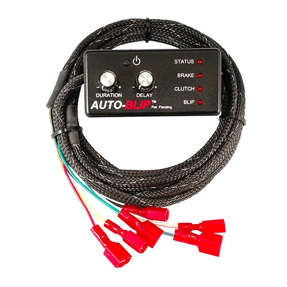
7. The “BLIP” LED turns on when a throttle blip event occurs. Note: The AUTO-BLIP will automatically turn OFF after 6 hours of inactivity. It will remain OFF until the ON/OFF button is pressed or power to the unit is removed and re-applied. - Page 11 In order for your AUTO-BLiP unit to function properly, you must first perform the calibration sequence outlined in this section!!! 1. Turn on ignition, but do not start engine. AUTO-BLiP “STATUS” LED light will light up. If not, turn ignition off and verify the power supply and ground connectors are fully seated.
-
Page 12: Tech Support
3. Be sure the unit has been calibrated, as outlined in the calibration section, according to your vehicle’s model and year. 4. Check harness for cuts, scrapes or abrasions. 5. Technical support: call (713)289-4015 (Mon-Fri from 9A-3P CST); email al@auto-blip.com Copyright © 2012 Tractive Technology, LLC. All rights reserved. Page 12... - Page 13 This warranty applies only to AUTO-BLiP product manufactured by Tractive Technology, LLC that can be identified by the "AUTO-BLiP" trademark, trade name, or logo affixed to them. This warranty does not cover damage resulting from an accident, misuse, abuse, or neglect and/or damage during any type of transportation resulting from improper packaging;...
Need help?
Do you have a question about the Lotus and is the answer not in the manual?
Questions and answers