Table of Contents
Advertisement
Quick Links
# G02772
®
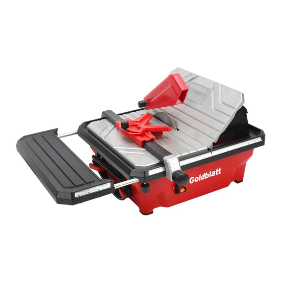
7 in.
4.6 A
180 mm
Tile Wet Saw
Español página 18
ATTACH YOUR RECEIPT HERE
Serial Number
Purchase Date
MNL_G02772_V02_20170328
Questions, problems, missing parts? Before returning to your retailer, call our customer
service department at 1-877-876-7562, 8 a.m. - 5 p.m.,CST, Monday - Friday.
Advertisement
Table of Contents

Related Manuals for Goldblatt TC180VI


Summary of Contents for Goldblatt TC180VI
- Page 1 # G02772 ® 7 in. 4.6 A 180 mm Tile Wet Saw Español página 18 ATTACH YOUR RECEIPT HERE Serial Number Purchase Date MNL_G02772_V02_20170328 Questions, problems, missing parts? Before returning to your retailer, call our customer service department at 1-877-876-7562, 8 a.m. - 5 p.m.,CST, Monday - Friday.
-
Page 2: Table Of Contents
TABLE OF CONTENTS Safety rules......................Safety symbols...................... Technical specifications..................Package Contents....................Assembly....................... Operation......................Maintenance......................Troubleshooting guide..................Warranty....................... -
Page 3: Safety Rules
SAFETY RULES WARNING To avoid serious personal injury, do not attempt to use this product until you read the manual thoroughly and understand it completely. Save this manual and review frequently for continuing safe operation and instructing others who may use this tool. - Page 4 SAFETY RULES 11. The product may be used only when in a faultless condition. If the product or part of the product is defective, have it repaired by an expert. 12. Always follow the applicable national and international safety, health and labour regulations.
- Page 5 SAFETY RULES 5. CHECK DAMAGED PARTS. Before further use of the tool, a guard or other part that is damaged should be carefully checked to determine that it will operate properly and perform its intended function - check for alignment of moving parts, binding of moving parts, breakage of parts, mounting, and any other conditions that may affect its operation.
- Page 6 SAFETY RULES 13. Make regular checks to ensure that the cutting disc is correctly fastened. 14. Make sure that during the cutting operation, an adequate quantity of cooling water reaches the cutting surfaces of the disc at all times. 15. Never cut wood or metal with this saw. 16.
- Page 7 SAFETY RULES RESIDUAL RISKS Even when the product is used properly and in compliance with all the safety precautions in these instructions for use, the following residual risks can arise: • Touching the cutting disc in the exposed area. • Reaching into the spinning cutting disc. •...
- Page 8 SAFETY RULES with or without yellow stripes is the equipment-grounding conductor. If repair or replacement of the electric cord or plug is necessary, do not connect the equipment-grounding conductor to a live terminal. Check with a qualified electrician or service personnel if the grounding instructions are not completely understood, or if in doubt as to whether the tool is properly grounded.
- Page 9 SAFETY RULES C. EXTENSION CORDS (FIG. C) Minimum gauge for extension cords (FIG. C) Volta Total length of cord in feet Ampere Rating 120 V 25 ft 50 ft 100 ft 150 ft More Than Not More Than Not Recommended 1.
-
Page 10: Safety Symbols
Waste electrical products should Wet conditions alert not be disposed of with household waste TECHNICAL SPECIFICATIONS Code G02772 Model TC180VI Voltage 120V~ 60Hz 4.6AMP No load speed 3590 RPM Insulation class Class I Dimensions of the diamond disc 7" x 5/8"... -
Page 11: Package Contents
PACKAGE CONTENTS PART DESCRIPTION QUANTITY Tile saw (assembled) Rip Fence Miter Guide Upper Blade Guard Saw Blade Metal Bracket Extension table and locking knob Water Reservoir Plug Sapnner ASSEMBLY This tile saw must only be used only to cut tiles to a required size or shape. It shall not be used to cut inflammable, explosive or toxic materials. - Page 12 ASSEMBLY Unpacking • Remove all packaging materials. • Remove remaining packing and package inserts (if included). • Check that the package contents are complete. • Check the appliance, the power cord, the power plug and all accessories for transportation damage. •...
- Page 13 ASSEMBLY INSTALLATION OF THE PROTECTIVE GUARD (Fig. 4) • Loosen the locking knob (1) and remove the locking knob, flat washer (2) and hex bolt (3) from the upper protective guard (4) • Align upper protective guard (4) with cutting disc and slide over metal bracket (5).
- Page 14 ASSEMBLY ANGLE OR BEVEL CUT (Fig. 7) • To perform 22.5° or 45° bevel cutting, raise one side of the table, lever out the support and locate the tabs into the corresponding holes in the deck. Ensure that the deck is correctly secured before working. fig.7 INSTALLING THE WATER RESERVOIR PLUG (Fig.
- Page 15 ASSEMBLY FILLING THE WATER RESERVOIR (Fig. 11) • Raise the 45° vertical fence approx. 45° and remove. • Push water reservoir plug into hole firmly. • Fill the reservoir with water only until water can drain from the opening in the plug.
-
Page 16: Operation
OPERATION MAKING A STRAIGHT CUT Adjust the parallel guide to the desired width. Use the securing knob to loosen or adjust the guide. Position the tile firmly against the parallel guide and pass through the blade in a smooth action. Hold the edges of the tile and press down firmly to prevent the tile lifting during the cut. -
Page 17: Warranty
TROUBLESHOOTING GUIDE POSSIBLE CORRECTIVE SYMPTOM CAUSE(S) ACTION Motor not running. No mains voltage? Check cable, plug, socket and fuse. Motor runs, cutting Flange nut loose? Check the flange is disc remains still seated correctly and when subject tighten if necessary. to load.
Need help?
Do you have a question about the TC180VI and is the answer not in the manual?
Questions and answers