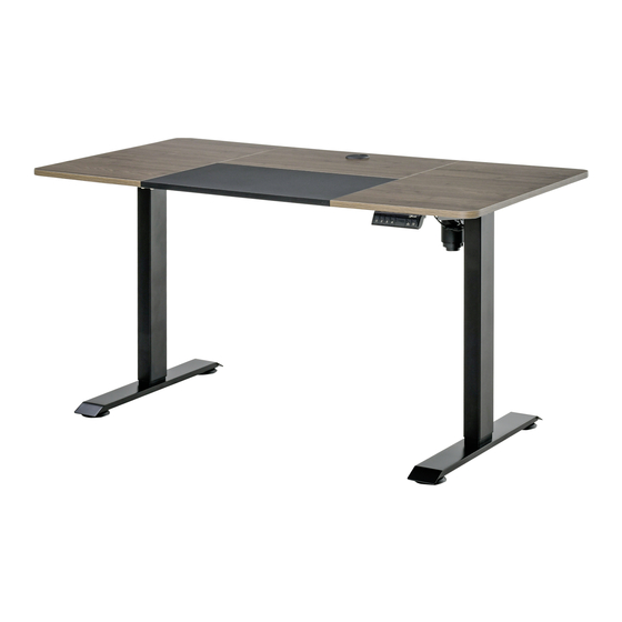
Summary of Contents for Vinsetto 920-071V70
- Page 1 INcfb039V01_UK 920-071V70 70KG Max 70kg IMPORTANT, RETAIN FOR FUTURE REFERENCE: READ CAREFULLY ASSEMBLY & INSTRUCTION MANUAL...
- Page 2 IMPORTANT SAFEGUARDS Read these instructions carefully and retain them for future use. When using the product, basic safety precautions should always be followed to reduce the risk of injury including the following: ●Unpack all hardware bags and components to ensure you have all the parts.
- Page 3 Parts List Lift column*1 Lift column*1 Base*2 Frame*2 Side bracket*2 Motor Rod*1 Desktop connection block*4 Desk top*4+Wooden pin*12 Power supply holder*1 ④ ① ② ③ 5# wrench*1 Handset + Power supply M6 screws*52 K M4 screws*1 cross screwdriver*1 Power cord L Tapping screws*4...
- Page 4 Assembly steps Step 1: 1.1 Connect the ①board and the ②board with wooden pins. Then connect ③ and ④ to the ①and ② tables with wooden pins. 1.2 Fasten connecting blocks with M6 screws as shown in the figure.M6 screws using the supplied spanner .
- Page 5 Step 3: 3.1 Assembling frame tightened with M6 screws.M6 screws using the supplied spanner 3.2 Then install the two side bracket with M6 screws.M6 screws using the supplied spanner Step 4: 4.1 Lay the table board flat and put it on the table shelf. 4.2 Attach M6 screws on the middle crossbar, but not taghten them frstly.M6 screws using the supplied spanner .
- Page 6 Step 5: 6.1 As shown in Figure 1, insert the hexagonal bar into the table leg B until the buckle is not visible. 6.2 Assemble the other end of the connecting rod to the table leg A and screw on the handle. The handle does not need to be tightened.
- Page 7 Operational instructions 1. Lift Column Press the button or button to control the lift column up or down Press the button to control up of the lifting column, you can see the height (displayed number) on the screen; press the button to control the down of the lifting column, you can see the height (displayed number) on the screen.


Need help?
Do you have a question about the 920-071V70 and is the answer not in the manual?
Questions and answers