Table of Contents
Advertisement
Quick Links
Advertisement
Table of Contents

Related Manuals for OneFex CS-02TR


Summary of Contents for OneFex CS-02TR
- Page 1 CS-02TR/04TR User Manual CS-02TR/CS-04TR Network IO Controller User Manual 1 / 21...
-
Page 2: Table Of Contents
CS-02TR/04TR User Manual Catalog Catalog ............................. 2 PRODUCT INTRODUCTION ....................4 FEATURES ........................4 PARAMETER ......................4 ITEM SELECTION ..................... 5 Dimension ........................5 Wiring Instructions ........................6 Terminal Definition ...................... 6 Power Supply ......................6 RS485 Connection ..................... 7 4G antenna/network cable connection .............. - Page 3 CS-02TR/04TR User Manual Notice ❖ Please read this manual carefully before use and save it for reference. ❖ Please follow to the operating procedures and precautions in this manual. ❖ Please open the package carefully and check whether the device and accessories have been damaged due to transportation when you receive the device.
-
Page 4: Product Introduction
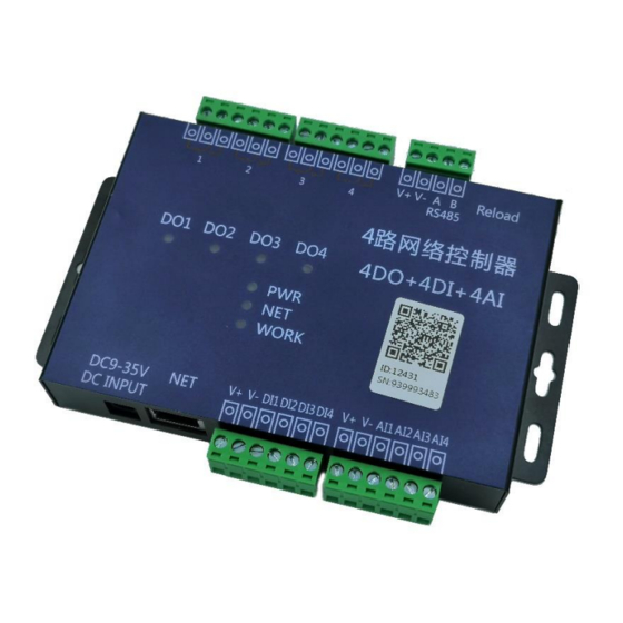
CS-02TR/04TR User Manual PRODUCT INTRODUCTION CS-02TR/04TR is network controller that integrates DO (digital output), DI (digital input), AI (analog input), and supports RS485/MODBUS protocol. The communication method supports Ethernet/Cat1 networking, RS485 interface, 9~24V wide voltage power supply, and supports functions such as logic control between analog acquisition and relay output. -
Page 5: Item Selection
CS-02TR/04TR User Manual √ √ √ √ NOLock Linkage √ √ √ √ Lock Linkage √ √ √ √ All Channel Lock Linkage √ √ √ √ 2Device NOLock Linkage √ √ √ √ 2Device Lock Linkage Electrical& Contact capacity... -
Page 6: Wiring Instructions
CS-02TR/04TR User Manual Wiring Instructions 2.1 Terminal Definition DI AI DO Terminal Definition Instruction DI INPUT VIN+ Positive power supply VIN- Negative power supply DCOM DI public terminal(=VIN-) Digital input1 Digital input2 AI INPUT Analog input1 Analog input2 DO OUTPUT... -
Page 7: Rs485 Connection
CS-02TR/04TR User Manual 2.3 RS485 Connection RS485 interface of the controller uses a 5mm terminal block. Support MODBUS RTU protocol for control. It can be connected to PC, PLC or configuration screen and other equipment for data acquisition and control. -
Page 8: Ai Wiring
CS-02TR/04TR User Manual 2.5 AI Wiring 2.6 DI Wiring Active Switch (Wet Contact): measuring signal with voltage (high and low level, pulse), such as infrared detection, triode output, liquid level detection, smoke detection, PLC output, flow monitoring. Passive Switch (Dry Contact): passive contact signal, such as various switches, buttons. -
Page 9: Do Wiring
CS-02TR/04TR User Manual 2.7 DO Wiring 9 / 21... -
Page 10: Communication Protocol And Data Format
CS-02TR/04TR User Manual Please add an AC contactor/intermediate relay between this device and the load in the following four cases: 1. Load rated voltage>30VDC 2. Load rated voltage>250VAC 3. Non-Resistive Load Current>3A 4. Resistive load current>5A Communication Protocol and Data Format 3.1 Manual and Software Updating... -
Page 11: Communication Setting
CS-02TR/04TR User Manual 3.2 Communication Setting 3.2.1 Device Address 3.2.2 Read/Set Baud Rate 3.3 Communication Protocol Instructions This controller supports standard Modbus commands. For detailed command generation and parsing methods, you can refer to "Modbus Protocol English Version" based on the register table in this article. This product supports Modbus-RTU format. -
Page 12: Modbus Register Instruction
CS-02TR/04TR User Manual 3.3.1 Modbus Register Instruction Register Type Function Type Explanation Defaults Address 03E8H uint16 Communication Baud Rate Read and write RS485 interface baud rate, default 9600; [0-9600; 1-2400; 2-4800; 3-9600; 4-19200; 5-115200] 03E9H uint16 Check Digit Read and write... - Page 13 CS-02TR/04TR User Manual then opens 4 outputs open and close loop 5 Close when greater than the upper limit, open when less than the lower limit 6 Open when greater than the upper limit, and close when it is less than...
-
Page 14: Storage Rules For Collecting Sensor Data
CS-02TR/04TR User Manual limit 9 Jog input, control output 04A1H uint16 TimeDelayOn Read and write Delay off time in seconds, mode 3, 4 04A2H uint16 TimeDelayOff Read and write Disconnect time in seconds, used in mode 4 04A3H uint16 LogicH... -
Page 15: Local Logic Mode
CS-02TR/04TR User Manual the sensor data of this round and the next round of sensor data, in ms, the default is 500ms, and the value range is 1~65535; (3) Slave acquisition time interval: in the process of collecting a round of sensors, the interval time for different sensors to collect data, in ms, the default is 500ms, and the value range is 1~65535;... -
Page 16: Active Reporting Protocol
CS-02TR/04TR User Manual the current relay state by bit 0001H uint16 switch status read only Switch status register, high byte is 00H The low byte indicates the current switch state by bit 0002H uint16 The first read only The first channel analog value... -
Page 17: Configuration Software Instructions
CS-02TR/04TR User Manual (1) If the client server actively reads the data, the required status register data can be read according to the standard Modbus RTU protocol 03H function code; (2) If uses active reporting function, the reporting protocol is as follows: Add 03 num aa aa bb bb cc cc dd dd xx xx .. - Page 18 CS-02TR/04TR User Manual ‘’ linkage Settings" can read and configure logical functions. “Node Settings” can read configuration of sensors and configure the corresponding Node address, function code, start address, and length of registers; controller can read the data of corresponding sensor in sequence according to configuration sequence.
-
Page 19: Product Maintenance
CS-02TR/04TR User Manual Product Maintenance 4.1 Device Usage Environment 1. The working voltage is 9~28V. If the input voltage is too high or too low, the device may not work normally or even be damaged. 2. The DI input terminal adopts optocoupler isolation protection, and its bearing voltage is 5~24V. -
Page 20: The Do Can Only Be Turned On But Not Turned Off
CS-02TR/04TR User Manual 4.2.2 The DO can only be turned on but not turned off Check Whether the read address reads the actual device address; Check whether there is a return command in the debug information column, and whether the return command is correct. -
Page 21: Plc And The Device Cannot Communicate Normally
After-sale Service 5.1 Commitment OneFex provides after-sales service of the device within one year from the date of sale. But for damage caused by improper use, you need to send it back and take the freight for repair or adjust. Make sure that the package is in good condition to avoid damage during transportation.
Need help?
Do you have a question about the CS-02TR and is the answer not in the manual?
Questions and answers