Table of Contents
Advertisement
Quick Links
Advertisement
Table of Contents

Related Manuals for OneFex CS-IO3200


Summary of Contents for OneFex CS-IO3200
- Page 1 CS-IO3200 User Manual CS-IO3200 Serial IO Controller Manual / 13...
-
Page 2: Table Of Contents
CS-IO3200 User Manual PRODUCT INTRODUCTION ....................5 Features ............................5 Parameter ............................5 Item Selection ..........................6 Dimension ............................6 Terminal Definition ......................... 6 Communication Wiring ........................9 RS485 Wiring ............................. 9 2.2.1 2.2.2 RS232 Wiring ............................. 9 DO Wiring ............................10 Low Load Wiring .......................... - Page 3 CS-IO3200 User Manual FAQ ..............................23 5.2.1 RS485 /RS232 communication, no response when device control ......... 23 The relay can only be turned on but not turned off ..............24 5.2.2 5.2.3 485 interface cannot be used to establish communication and control After the relay powered on.
- Page 4 CS-IO3200 User Manual Notice ❖ Please read this manual carefully before use and save it for reference. ❖ Please follow to the operating procedures and precautions in this manual. ❖ Please open the package carefully and check whether the device and accessories have been damaged due to transportation when you receive the device.
-
Page 5: Product Introduction
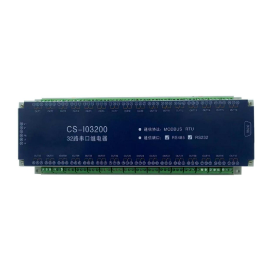
CS-IO3200 User Manual Product Introduction CS-IO series products are IO controller using standard Modbus-RTU protocol, supporting RS485/232. Support wide voltage power supply, multi-channel input and output control, which can be widely used in various application scenarios such as industrial production, agriculture, smart city and office buildings. -
Page 6: Item Selection
CS-IO3200 User Manual Din Rail Installation 35mm Din Rail Mounting / Screw Holes 1.3 Item Selection Item # Analog RS485 Address Dial CS-IO101 RS485 * 1 Address Dial CS-IO204 RS485 * 1 Address Dial CS-IO222A 2(0-20mA) RS485 * 1 Address Dial... - Page 7 CS-IO3200 User Manual Normally OFF The 29 DO normally OFF terminal Normally ON The 28 DO normally ON terminal Public The 28 DO public terminal Normally OFF The 28 DO normally OFF terminal Normally ON The 27 DO normally ON terminal...
- Page 8 CS-IO3200 User Manual Normally OFF The 17 DO normally OFF terminal Normally ON The 16 DO normally ON terminal Public The 16 DO public terminal Normally OFF The 16 DO normally OFF terminal Normally ON The 15 DO normally ON terminal...
-
Page 9: Communication Wiring
CS-IO3200 User Manual Normally OFF The 5 DO normally OFF terminal Normally ON The 4 DO normally ON terminal Public The 4 DO public terminal Normally OFF The 4 DO normally OFF terminal Normally ON The 3 DO normally ON terminal... -
Page 10: Do Wiring
CS-IO3200 User Manual 2.3 DO Wiring The relay is single-pole, double-throw, and each circuit has three terminals, one group is normally ON and the other is normally OFF (normally ON contacts are generally used), and the terminal identification is subject to the indications on the film. -
Page 11: Ac 380V Load Device Wiring 【With Zero Line
CS-IO3200 User Manual AC 380V Load Device Wiring 【With Zero Line】 2.3.3 2.3.4 AC 380V Load Device Wiring【Without Zero Line】 Please add an AC contactor/intermediate relay between this device and the load in the following four cases: 1. Load rated voltage>30VDC 2. -
Page 12: Dc Load Device Wiring
CS-IO3200 User Manual 2.3.5 DC Load Device Wiring Parameters and Working Mode Configuration 3.1 Device and PC Connection Settings The USB end of the USB to RS485/RS232 converter is directly connected to the USB port of computer, and 485/232 end is wired according to the wiring method in "Chapter 2.2 Communication Wiring". -
Page 13: Device Communication Address Reading
CS-IO3200 User Manual 3.2.1 Device Communication Address Reading After the device is connected normally, click "read address" on the serial relay debugging software to read the current address of the device [only support broadcast read address when there is one device on the bus]. -
Page 14: Baud Rate Reading And Setting
CS-IO3200 User Manual 3.2.3 Baud Rate Reading and Setting Click "Read" and "Set" to read and set the baud rate and address respectively, which will take effect immediately after the operation. Development Data Instruction 4.1 Communication Protocol Instruction This product supports standard Modbus commands. For detailed command generation and parsing methods, you can refer to "MODBUS Protocol English... - Page 15 CS-IO3200 User Manual Coil Control 7 00007 The 7th DO Coil Control 8 00008 The 8th DO Coil Control 9 00009 The 9th DO Coil Control 10 00010 The 10th DO Coil Control 11 00011 The 11th DO Coil Control 12...
- Page 16 CS-IO3200 User Manual Parameters Configuration Modbus Explaination Register Register address address Communication 03E8H 41001 See the below corresponding baud rate table of baud rate values, the default value is 0, and supports 0-5. This register determines the Holding communication baud rate of...
-
Page 17: Command List
CS-IO3200 User Manual 4.3 Command List Scene RTU format (send in hexadecimal) Query 32 DOs ‘status FE 01 00 00 00 20 29 DD Return query information FE 01 04 00 00 00 00 F4 DE FE 05 00 00 FF 00 98 35... - Page 18 CS-IO3200 User Manual FE 05 00 0B 00 00 A8 07 Control the 12 DO off FE 05 00 0C FF 00 58 36 Control the 13 DO on FE 05 00 0C 00 00 19 C6 Control the 13...
-
Page 19: Command Details
CS-IO3200 User Manual FE 05 00 1A 00 00 F8 02 Control the 27 DO off FE 05 00 1B FF 00 E8 32 Control the 28 DO on FE 05 00 1B 00 00 A9 C2 Control the 28... -
Page 20: Query Do Status
CS-IO3200 User Manual 4.4.2 Query DO Status Sending Code:FE 01 00 00 00 20 29 DD Field Meaning Note Device address It is the broadcast address 01 command Query DO status command 00 00 Starting address Register address of the first DO to be queried... - Page 21 CS-IO3200 User Manual Interval time 00 0A is 10 (hexadecimal converted to decimal) 00 0A The interval time is (0.1 seconds*10) 41 6B /A1 6A CRC16 Check method Return code:FE 10 00 03 00 02 A5 C7 Field Meaning Note...
-
Page 22: All On And All Off Command
CS-IO3200 User Manual channel flash ON command: FE 10 00 44 00 02 04 00 02 00 0A E4 BC channel flash ON command: FE 10 00 49 00 02 04 00 02 00 0A 25 25 channel flash ON command: FE 10 00 4E 00 02 04 00 02 00 0A 64 C3 4.4.4... -
Page 23: Product Maintenance
CS-IO3200 User Manual Product Maintenance 5.1 Device Usage Environment 1. The working voltage is DC 12/24V. If the input voltage is too high or too low, the device may not work normally or even be damaged. 2. The DI input terminal adopts optocoupler isolation protection, and its bearing voltage is 5~24V. -
Page 24: The Relay Can Only Be Turned On But Not Turned Off
CS-IO3200 User Manual 5.2.2 The relay can only be turned on but not turned off Check Whether the read address reads the actual device address; Check whether there is a return command in the debug information column, and whether the return command is correct. -
Page 25: After-Sale Service
After-sale Service 6.1 Commitment OneFex provides after-sales service of the device within one year from the date of sale. But for damage caused by improper use, you need to send it back and take the freight for repair or adjust. Make sure that the package is in good condition to avoid damage during transportation.
Need help?
Do you have a question about the CS-IO3200 and is the answer not in the manual?
Questions and answers