Table of Contents
Advertisement
Quick Links
Advertisement
Table of Contents

Related Manuals for OneFex CS-IO222A


Summary of Contents for OneFex CS-IO222A
-
Page 1: Cs-Io222A
CS-IO222A User Manual CS-IO222A Serial IO Controller Manual / 13... -
Page 2: Table Of Contents
CS-IO222A User Manual CS-IO222A ..............................1 PRODUCT INTRODUCTION ......................5 ............................5 EATURES ............................5 ARAMETER ........................... 6 ELECTION ............................6 IMENSION WIRING INSTRUCTIONS ........................7 .......................... 7 ERMINAL EFINITION ........................7 OMMUNICATION IRING 2.2.1 RS485 Wiring ..........................7 ............................7... - Page 3 CS-IO222A User Manual RS485 /RS232 communication, no response when device control ........21 5.2.1 5.2.2 The relay can only be turned on but not turned off ..............22 5.2.3 485 interface cannot be used to establish communication and control After the relay powered on.
- Page 4 CS-IO222A User Manual Notice ❖ Please read this manual carefully before use and save it for reference. ❖ Please follow to the operating procedures and precautions in this manual. ❖ Please open the package carefully and check whether the device and accessories have been damaged due to transportation when you receive the device.
-
Page 5: Product Introduction
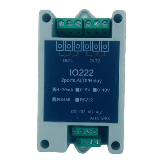
CS-IO222A User Manual Product Introduction CS-IO series products are IO controller using standard Modbus-RTU protocol, supporting RS485/232. Support wide voltage power supply, multi-channel input and output control, which can be widely used in various application scenarios such as industrial production, agriculture, smart city and office buildings. -
Page 6: Item Selection
CS-IO222A User Manual Flash ON Flash OFF All ON All OFF Functions NOLock Linkage Lock Linkage Interlock 2Device NOLock Linkage 2Device Lock Linkage Working mode change DO independent control Software support DI status query Overall DO control; Debugging information query;... -
Page 7: Wiring Instructions
CS-IO222A User Manual Wiring Instructions 2.1 Terminal Definition Instruction Positive Power Supply Negative Power Supply RS485 communication A+ RS485 communication B- Normally ON The 2 DO normally ON terminal Public The 2 DO public terminal Normally OFF The 2 DO normally ON terminal... -
Page 8: Low Load Wiring
CS-IO222A User Manual The relay is single-pole, double-throw, and each circuit has three terminals, one group is normally ON and the other is normally OFF (normally ON contacts are generally used), and the terminal identification is subject to the indications on the film. -
Page 9: Ac 380V Load Device Wiring 【With Zero Line
CS-IO222A User Manual 2.3.3 AC 380V Load Device Wiring 【With Zero Line】 2.3.4 AC 380V Load Device Wiring【Without Zero Line】 Please add an AC contactor/intermediate relay between this device and the load in the following four cases: 1. Load rated voltage>30VDC 2. -
Page 10: Analog Input Wiring
CS-IO222A User Manual smoke detection, PLC output, flow monitoring. It is suitable for passive contact signal, such as various switches, buttons, etc. 2.5 Analog Input Wiring Parameters and Working Mode Configuration 3.1 Device and PC Connection Settings The USB end of the USB to RS485 converter is directly connected to the USB port of computer, and 485end is wired according to the wiring method in "Chapter... -
Page 11: Device Communication Address Reading
CS-IO222A User Manual With DIP switch, users can quickly modify the device address. (1)The address is "31" when all 5 dial codes are dialed above; (2) The address is "0" When all t5 dial codes are dialed below; (3) The leftmost 1 is the lowest digit in binary;;... -
Page 12: Baud Rate Reading And Setting
CS-IO222A User Manual 3.2.4 Baud Rate Reading and Setting Click "Read" and "Set" to read and set the baud rate and address respectively, which will take effect immediately after the operation. 3.3 Working Mode 3.3.1 Normal Mode The relay takes corresponding actions after ON/OFF command. -
Page 13: Lock Linkage Mode
CS-IO222A User Manual 3.3.3 Lock Linkage Mode In this mode, each time the optocoupler inputs a signal, the corresponding relay is flipped once. The optocoupler input signal takes effect -> the relay flips (the pull-in changes to disconnect, the disconnect changes to pull-in);... -
Page 14: 2Device Lock Linkage Mode
CS-IO222A User Manual control the alarm lights or bells, it is only necessary to arrange a few modules in the workshop and connect them to the corresponding modules in the machine room through two twisted-pair shielded cables. can complete this task. In the same way, the button signal of the computer room operation can also be directly transmitted to the relay located in the computer room module. -
Page 15: Modbus Register Instruction
CS-IO222A User Manual generation and parsing methods, you can refer to "MODBUS Protocol English Version" based on the register table in this article. This product supports Modbus RTU format. 4.2 Modbus Register Instruction Instruction code Meaning Read coil register [DO]... -
Page 16: Command List
CS-IO222A User Manual 40001 to 49999 are holding registers (usually store device configuration information) In 5-bit code format, the first character determines register type, and the remaining 4 characters represent address. Address 1 starts from 0, such as 00001 corresponds to 0000. -
Page 17: Command Details
CS-IO222A User Manual FE 05 00 00 00 00 D9 C5 Control the 1 DO off FE 05 00 00 00 00 D9 C5 Return control information FE 05 00 01 FF 00 C9 F5 Control the 2 DO on... -
Page 18: Optocoupler Input
CS-IO222A User Manual DO return information: Return code: FE 01 01 00 61 9C Field Meaning Note Device address 01 command Return command: If the query is wrong, return 0x81 Number of bytes All bytes of return status information. 1+(n-1)/8 Status of the query Returns the DO status. -
Page 19: Ai Query
CS-IO222A User Manual 4.4.4 AI Query Query AI data (2 channels, 0~20mA) The relationship between the obtained analog data and actual input value is: Actual value=Return value * 0.001 Send command code: FE 04 00 00 00 02 65 C4... -
Page 20: All On And All Off Command
CS-IO222A User Manual individually 00 04 / 00 02 Command 00 04: flash OFF command 00 02: flash ON command 00 0A Interval time 00 0A is 10 (hexadecimal converted to decimal) The interval time is (0.1 seconds*10) 41 6B /A1 6A CRC16 Check method Return code:FE 10 00 03 00 02 A5 C7... -
Page 21: Active Reporting Protocol
CS-IO222A User Manual Return code:FE 0F 00 00 00 02 C0 05 Field Meaning Note Device address 0F command Return command: If the query is wrong, return 0x82 Starting address 00 00 00 02 Quantity Number of DOs returning information... - Page 22 CS-IO222A User Manual addresses; Confirm whether the serial port number on the software is correct; Check whether the power supply and work indicator are normal; For the RS232 version, please correctly identify the RS232 serial port module used as male or female.
- Page 23 After-sale Service 6.1 Commitment OneFex provides after-sales service of the device within one year from the date of sale. But for damage caused by improper use, you need to send it back and take the freight for repair or adjust. Make sure that the package is in good condition to avoid damage during transportation.
- Page 24 CS-IO222A User Manual Update History Date Update Content Version Create document 2019/05/27 V1.0.1 Update wiring 2020/02/01 V1.1.0 diagrams, etc. Update description 2020/07/29 V1.2.0 / 13...
Need help?
Do you have a question about the CS-IO222A and is the answer not in the manual?
Questions and answers