Table of Contents
Advertisement
Quick Links
Operator's Manual
Installation, Operation and Maintenance Instructions
HE6W8-PP-QSF2.8-T120-SA
PLEASE READ CAREFULLY
YOUR WARRANTY MAY BE VOID IF INSTRUCTIONS ARE NOT FOLLOWED
Premier Pump and Power, LLC
PO Box 6423
th
7600 NE 47
Ave.
Vancouver, WA 98668-6423
Phone: 360-574-4519
Fax: 772-679-5989
www.wastewaterpumps.net
Page | 1
Advertisement
Table of Contents

Subscribe to Our Youtube Channel
Related Manuals for Premier pump & power HE6W8-PP-QSF2.8-T120-SA

Summary of Contents for Premier pump & power HE6W8-PP-QSF2.8-T120-SA
- Page 1 Operator’s Manual Installation, Operation and Maintenance Instructions HE6W8-PP-QSF2.8-T120-SA PLEASE READ CAREFULLY YOUR WARRANTY MAY BE VOID IF INSTRUCTIONS ARE NOT FOLLOWED Premier Pump and Power, LLC PO Box 6423 7600 NE 47 Ave. Vancouver, WA 98668-6423 Phone: 360-574-4519 Fax: 772-679-5989 www.wastewaterpumps.net...
-
Page 2: Table Of Contents
CONTENTS Page Number NHTSA Notification Statement ..............3 Tire Safety Information ................. 4 Replacement Parts Request and Vintag Location ........21 Premier Pump Warranty ................22 Premier Pump Warranty Procedure ............25 Unit External Dimensions ................26 Overview of Pump Design ................27 Freezing Weather Effect on Pump Systems ..........33 Operation of the Pump ................34 Pump Performance Curve ................36 Pre-Start Checklist ..................37... -
Page 3: Nhtsa Notification Statement
Troubleshooting the Priming System............55 Wheel Mounting and Torque Specifications ..........56 Wire Diagram for Single Axle ..............57 Jack Components and Dimensions .............58 Discharge Check Valve Dimensions ............59 Operation, Maintenance and Installation Manual (Val-Matic) ......60 Assembly Drawing with IPB ................68 NHTSA Notification Statement If you believe that your vehicle has a defect that could cause a crash or could cause injury or death, you should immediately inform the National Highway Traffic Safety Administration (NHTSA) in addition to notifying ABC Manufacturing Inc. -
Page 4: Tire Safety Information
TIRE SAFETY INFORMATION This portion of the User’s Manual contains tire safety information as required by 49 CFR 575.6. Section 1.1 contains “Steps for Determining Correct Load Limit - Trailer”. Section 1.2 contains “Steps for Determining Correct Load Limit – Tow Vehicle”. Section 1.3 contains a Glossary of Tire Terminology, including “cold inflation pressure”, “maximum inflation pressure”, “recommended inflation pressure”, and other non- technical terms. - Page 5 C. Adverse safety consequences of overloading on handling and stopping on tires. 1.1 STEPS FOR DETERMINING CORRECT LOAD LIMIT – TRAILER Determining the load limits of a trailer includes more than understanding the load limits of the tires alone. On all trailers there is a Federal certification/VIN label that is located on the forward half of the left (road) side of the unit.
- Page 6 1.1.1. TRAILERS 10,000 POUNDS GVWR OR LESS Tire and Loading Information Placard – Figure 1-1 1. Locate the statement, “The weight of cargo should never exceed XXX kg or XXX lbs.,” on your vehicle’s placard. See figure 1-1. 2. This figure equals the available amount of cargo and luggage load capacity. 3.
- Page 7 Subtract the combined weight of the driver and passengers from XXX kilograms or XXX pounds. The resulting figure equals the available amount of cargo and luggage capacity. For example, if the “XXX” amount equals 1400 lbs. and there will be five 150 lb. passengers in your vehicle, the amount of available cargo and luggage capacity is 650 lbs.
- Page 8 Cord The strands forming the plies in the tire. Cord separation The parting of cords from adjacent rubber compounds. Cracking Any parting within the tread, sidewall, or inner liner of the tire extending to cord material. A pneumatic tire with an inverted flange tire and rim system in which the rim is designed with rim flanges pointed radially inward and the tire is designed to fit on the underside of the rim in a manner that encloses the rim flanges inside the air cavity of the tire.
- Page 9 Intended outboard sidewall The sidewall that contains a white-wall, bears white lettering or bears manufacturer, brand, and/or model name molding that is higher or deeper than the same molding on the other sidewall of the tire or the outward facing sidewall of an asymmetrical tire that has a particular side that must always face outward when mounted on a vehicle.
- Page 10 Non-pneumatic tire assembly A non-pneumatic tire, alone or in combination with a wheel or wheel center member, which can be mounted on a vehicle. Normal occupant weight This means 68 kilograms (150 lbs.) times the number of occupants specified in the second column of Table I of 49 CFR 571.110.
- Page 11 Recommended inflation pressure This is the inflation pressure provided by the vehicle manufacturer on the Tire Information label and on the Certification / VIN tag. Reinforced tire A tire designed to operate at higher loads and at higher inflation pressures than the corresponding standard tire.
- Page 12 Tread separation Pulling away of the tread from the tire carcass. Treadwear indicators (TWI) The projections within the principal grooves designed to give a visual indication of the degrees of wear of the tread. Vehicle capacity weight The rated cargo and luggage load plus 68 kilograms (150 lbs.) times the vehicle’s designated seating capacity.
- Page 13 irregularities are the most important things you can do to avoid tire failure, such as tread separation or blowout and flat tires. These actions, along with other care and maintenance activities, can also: • Improve vehicle handling. • Help protect you and others from avoidable breakdowns and accidents. •...
- Page 14 Both placards and certification labels are permanently attached to the trailer near the left front. 1.5.2. UNDERSTANDING TIRE PRESSURE AND LOAD LIMITS Tire inflation pressure is the level of air in the tire that provides it with load-carrying capacity and affects the overall performance of the vehicle. The tire inflation pressure is a number that indicates the amount of air pressure –...
- Page 15 1.5.4. STEPS FOR MAINTAINING PROPER TIRE PRESSURE • Locate the recommended tire pressure on the vehicle's tire information placard, certification label, or in the owner's manual. • Record the tire pressure of all tires. • If the tire pressure is too high in any of the tires, slowly release air by gently pressing on the tire valve stem with the edge of your tire gauge until you get to the correct pressure.
- Page 16 built-in treadwear indicators that let you know when it is time to replace your tires. These indicators are raised sections spaced intermittently in the bottom of the tread grooves. When they appear "even" with the outside of the tread, it is time to replace your tires.
- Page 17 Next number This two-digit number, known as the aspect ratio, gives the tire's ratio of height to width. Numbers of 70 or lower indicate a short sidewall for improved steering response and better overall handling on dry pavement. The "R" stands for radial. Radial ply construction of tires has been the industry standard for the past 20 years.
- Page 18 numbers 3197 means the 31st week of 1997. The other numbers are marketing codes used at the manufacturer's discretion. This information is used to contact consumers if a tire defect requires a recall. Tire Ply Composition and Materials Used The number of plies indicates the number of layers of rubber-coated fabric in the tire. In general, the greater the number of plies, the more weight a tire can support.
- Page 19 Tires for light trucks have other markings besides those found on the sidewalls of passenger tires. The "LT" indicates the tire is for light trucks or trailers. An "ST" is an indication the tire is for trailer use only. Max. Load Dual kg (lbs.) at kPa (psi) Cold This information indicates the maximum load and tire pressure when the tire is used as a dual, that is, when four tires are put on each rear axle (a total of six or more tires on the vehicle).
-
Page 20: Replacement Parts Request And Vintag Location
REPLACEMENT PARTS REQUEST AND VINTAG LOCATION Requests for replacement parts and any questions regarding this machinery should be directed toward the manufacturer’s sales department. Numerous revisions to the design of the equipment continue to be made due to our ongoing commitment to improve form and function. Serial numbers of the engine or pump and the Mfg. - Page 21 P.O. Box 6423 Vancouver, WA 98668 Phone (360) 574-4519 Fax (772) 679-5989 www.wastewaterpumps.net Conditions and terms of sale causes shall continue for a period of sixty (60) days. Under no circumstances shall Controlling provisions: These terms seller be liable for any special or and conditions shall control with respect consequential damages or for loss, to any purchase order or sale of sellers’...
- Page 22 relieve seller of all further obligation other which case same will be credited subject than as expressed in seller’s product to the following: (a) All material must on its arrival at seller’s facility, be found in warranty. THIS IS SELLERS SOLE WARRANTY.
- Page 23 • Minimum invoice amount will be no re-submitted to the customer for their acceptance or refusal. All quotations are less than $25.00 plus transportation. valid for 30 days from the date on the quotation. Use of equipment: Buyer agrees to maintain and use the equipment solely in Prices and designs: Prices and designs the conduct of its own business, in a...
- Page 24 Page | 24...
-
Page 25: Premier Pump Warranty
Warranty Procedure STEP 1 STEP 4 Customer initiates contact with Premier sales representative Once the product has been received by Premier, it will explaining the issues they are having with the product. be evaluated to determine if warranty is approved or denied. STEP 2 •... -
Page 26: Unit External Dimensions
Page | 26... -
Page 27: Overview Of Pump Design
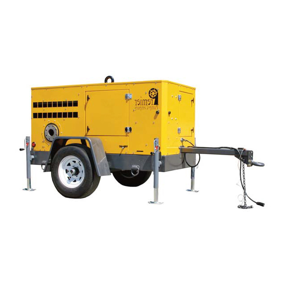
OVERVIEW OF PUMP DESIGN The Premier Pump HE6W8-PP-QSF2.8-T120-SA series is an automatic self-priming pump driven by a diesel engine. Specifically designed to handle abrasive fluids such as sewage and sludge containing solids, it provides a dependable, high efficiency solution for your pumping requirements. The pump has proven itself fully capable in a variety of applications including those with intermittent flow conditions, and both open and sewage by-pass applications where a moderate amount of air handling is required. - Page 28 The 5-position channel on the tongue of the trailer accepts a variety of towing couplers. Pictured is a lunette eye, that mates with a pintle hitch on the tow vehicle. Ball couplers of various sizes may likewise be fitted. Regardless which is used you must ensure the trailer is level to prevent “fishtailing”...
- Page 29 A lifting bail/eye has been included and is the only attachment point strong enough for lifting and/or suspension. Appropriate lifting gear; shackles and straps are not supplied. D-rings are located on each corner of the trailer to provide adequate tie-down points for extreme weather conditions and can also be useful tie-down points when transporting the unit on a flatbed trailer.
- Page 30 ENGINE The units come standard with an adequately powered diesel engine rigidly mounted to the chassis. The engine will automatically derate whenever a low oil pressure or high coolant temperature condition occurs. Do not restart the engine without first identifying the source of the problem.
- Page 31 One of the main functions of the mechanical seal is to prevent air or pumping liquid with gritty particles being drawn into the back of the pump through the stuffing box. When servicing or replacing the seal, it is essential that precautions are taken to assure that the seal chamber is kept free of dirt.
- Page 32 PRIMING SYSTEM Priming may be accomplished by the Premier-Prime (PP) fully automatic priming/repriming system. The belt driven diaphragm vacuum pump (18) evacuates air from the pump and its suction hose causing the water column to rise and flood the pump, and operates whenever the engine is running.
-
Page 33: Freezing Weather Effect On Pump Systems
FREEZING WEATHER EFFECT ON PUMP SYSTEMS During freezing weather conditions, precautions must be taken to prevent pump system failure and damage. The following recommendations should be considered when operating pumps where the temperature does not exceed 32°F or 0°C. During down time, ensure the volute of the pump and suction line are drained. -
Page 34: Operation Of The Pump
OPERATION OF THE PUMP Consider the need for fluid containment and then erect or install in accordance with your company policy, job site work requirements and Environmental Protection Agency guidelines. The pump can be throttled by fitting an appropriate valve (butterfly, pinch or knife) to the discharge side of the pump. - Page 35 With pump properly leveled, and plumbed, ensure all suction and discharge piping is sufficiently supported (cribbed) to prevent stress on the pump and pipe or hose flange/clamping mechanisms. Material must be placed on a firm level base or foundation to properly disperse the weight of the load.
-
Page 36: Pump Performance Curve
Page | 36... -
Page 37: Pre-Start Checklist
PRE-START CHECKLIST ✓ Fill the tank with the appropriate type of diesel fuel. ✓ Check the fuel/water separator for contaminants & drain. Page | 37... - Page 38 ✓ Check the engine oil level. ✓ Check engine coolant level via the radiator cap. DANGER: Use caution when removing due to extremely hot and pressurized fluid. ✓ Ensure the fan/alternator drive belt is tight. ✓ Ensure the safety guards are secure and in place.
- Page 39 ✓ Check the oil level in the pump’s mechanical cartridge seal reservoir (ISO46 hydraulic fluid). ✓ Check the oil level in the pump’s bearing housing (ISO100 hydraulic fluid). ✓ Ensure ball valve on bottom of pump casing is closed. ✓ Ensure ball valve on the hose that is located between the air compressor or vacuum pump and the suction spool is open.
-
Page 40: Starting The Engine
STARTING THE ENGINE 1. Alert everyone in the vicinity that you are going to begin operations. 2. Don adequate Personal Protective Equipment (safety glasses, hard hat, steel toed shoes, etc.). 3. Ensure pumpage fluid is available at the suction end of the pump, open the priming isolation valve (unless you have a flooded suction application). -
Page 41: Starting The Engine Using The Autostart Controller
STARTING THE ENGINE USING THE AUTOSTART CONTROLLER When equipped, the AutoStart controller is designed to automatically start and stop the engine. Designed for use in combination with widely available common ground contact switches or submersible liquid level transmitters producing a 4-20mA signal. Either can be purchased separately from the manufacturer. - Page 42 If you care to test for proper operation you may do the following: 1. Program control panel for “Dual Switch Empty”. 2. Rotate ignition switch to Auto Start; green standby LED illuminates, unit self-tests. 3. RPM will indicate _ _ _. 4.
- Page 43 7. Jumper the terminals of the female connector (located at the rear of the cabinet on the footer) to complete the Auto Switch 1 circuit. NOTE: Curvature of ground (Gd) terminal. 8. Observe the enabling of the low float indicator on the control panel. Page | 43...
- Page 44 9. Jumper the male connector (plug) terminals together to complete the Auto Switch 2 circuit. 10. Observe the enabling of the high float indicator on the control panel. 11. The RPM will now indicate 000 rather than _ _ _. 12.
-
Page 45: General Maintenance Guidelines
GENERAL MAINTENANCE GUIDELINES For periodic maintenance and repair/troubleshooting, please consult the owner/operator manuals for the engine, pump and/or control panel. They were shipped with the machine and should be found inside the document holder. Replacements may be requested from the manufacturer. At regular intervals check for any slight increase in noise or heat that may develop in any part of the pump, including the coupling, stuffing box, and bearings. -
Page 46: Maintenance Safety Instructions
MAINTENANCE SAFETY INSTRUCTIONS WARNING!! Improper practices or carelessness can cause burns, cuts, mutilation, asphyxiation or other bodily injury and even death. Read and seek clarification of all safety precautions and warnings before performing any repair. This list contains the general safety precautions that must be followed for personal safety. - Page 47 pressure when disconnecting any device from a system that utilizes pressure. Do not check for pressure leaks with your hand. High-pressure oil or fuel systems can cause personal injury. • To avoid personal injury, use a hoist or get assistance when lifting components that weigh 23 kg [50 lb.] or more.
-
Page 48: Eliminating Pump Problems
ELIMINATING PUMP PROBLEMS Does your pump make popping sounds, or sound like it's pumping marbles? Simply defined, cavitation is the formation of bubbles or cavities in liquid, developed in areas of relatively low pressure around an impeller. The imploding or collapsing of these bubbles trigger intense shockwaves inside the pump, causing significant damage to the impeller and/or the pump housing. - Page 49 When a pump's discharge pressure is extremely high or runs at less than 10% of its best efficiency point (BEP), discharge cavitation’s occur. The high discharge pressure makes it difficult for the fluid to flow out of the pump, so it circulates inside the pump. Liquid flows between the impeller and the housing at very high velocity, causing a vacuum at the housing wall and the formation of bubbles.
- Page 50 between the seal and its respective seat must be prevented. Minute amounts of dirt or grease that come from handling a seal with unsanitary hands can result in misalignment. Damaged seal due to improper installation. Suction and discharge piping must be correctly sized and designed to prevent the degradation of pump performance.
-
Page 51: Troubleshooting The Engine
TROUBLESHOOTING THE ENGINE Problem Possible causes Possible solutions Check the engine cranking speed with a handheld tachometer. If Engine cranking speed is too low the cranking speed is less than 150 rpm, refer to engine manual Engine cranks, will not start, Bleed the fuel system and check Air in the fuel system producing... - Page 52 Turbocharger malfunction Check for proper operation Fuel injector pump timing is not Adjust injector timing. correct Coolant Inspect for leaks and repair, then temperature is Coolant level is low replace lost coolant above normal Radiator fins are damaged or Inspect, clean and repair obstructed with debris Cooling system hose is Inspect the radiator hoses...
- Page 53 Change to heavier viscosity Viscosity is too light (thin) (thicker) High Oil Check gaskets, lines and drain Oil leaks Consumption plugs Defective turbocharger See authorized engine dealer Engine runs Verify operation of engine with rough or Fuel contaminated clean fuel in a temporary tank misfires Bleed the fuel system and check Air in the fuel...
-
Page 54: Troubleshooting The Pump
TROUBLESHOOTING THE PUMP Problem Possible causes Possible solutions Pump is not primed Check the priming system Run engine at required Speed too low power/speed Sum of suction and discharge Check the total head head greater than rated head of requirements against pump pump performance curve No liquid... - Page 55 Check engine and pump end Engine and/or pump end are mountings, tighten mounting bolts loose if necessary Impeller partially plugged Clean debris Inspect for replacement: Shaft, Mechanical defects Bearings, Wear rings, Impeller Suction or discharge pipe not Secure the suction and discharge anchored piping as necessary Pump is cavitating...
- Page 56 WHEEL MOUNTING & TORQUE SPECIFICATION It is extremely important to apply and maintain proper wheel mounting torque on your trailer axle. Torque wrenches are the only method to assure that the proper amount of torque is being applied to a fastener. Be sure to use only fasteners matched to the cone angle of your wheel and follow all wheel manufacturers recommended installation and torque requirements.
- Page 57 Page | 57...
- Page 58 JACK COMPONENTS AND DIMENSIONS (HD25000101) Designed for use with marine and utility trailers, Fulton brand tongue jacks are time- tested and application-proven. Our bolt-on versions include all necessary mounting hardware. For weld- on applications, we offer two styles of mounts for both 1/2"...
- Page 59 Page | 59...
- Page 60 Page | 60...
- Page 61 Page | 61...
- Page 62 Page | 62...
- Page 63 Page | 63...
- Page 64 Page | 64...
- Page 65 Page | 65...
- Page 66 Page | 66...
- Page 67 Page | 67...
- Page 68 Page | 68...
- Page 69 Page | 69...
- Page 70 Page | 70...
- Page 71 Page | 71...
- Page 72 Page | 72...
- Page 73 Page | 73...
- Page 74 Page | 74...
- Page 75 Page | 75...
- Page 76 Page | 76...
- Page 77 Page | 77...
- Page 78 Page | 78...
Need help?
Do you have a question about the HE6W8-PP-QSF2.8-T120-SA and is the answer not in the manual?
Questions and answers