
Subscribe to Our Youtube Channel
Related Manuals for Hysolis PPSiL Series


Summary of Contents for Hysolis PPSiL Series
- Page 1 OWNER'S MANUAL Smart Mobile POWER PPSiL Series PPS1000iL / PPS1500iL / PPS2000iL VER1.0-20201022...
-
Page 2: Table Of Contents
CONTENT 1. UNIT DESCRIPTION ................- 3 - 1.1 COMPONENTS IDENTIFICATION ..........- 3 - 1.2 OUTPUT PANEL ................- 4 - 1.3 CHARGING INPUT PANEL............. - 6 - 1.4 BATTERY CONNECTOR ..............- 6 - 2. - Page 3 INTRODUCTION Congratulations on your selection of a marvelous mobile power. This manual will provide you with a good basic understanding of the safe operation and maintenance of this machine, please read it carefully. Read this manual carefully before operating this mobile power. This manual should stay with this generator if it is sold.
-
Page 4: Unit Description
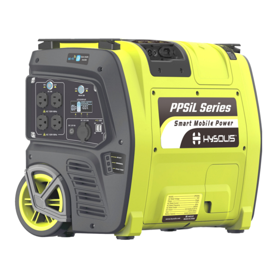
1. UNIT DESCRIPTION 1.1 COMPONENTS IDENTIFICATION (1). Output Panel: Location of mobile power controls and output receptacles. (2). Charging Input Panel: Location of mobile power charging input receptacles. (3). Maintenance Cover: Remove the cover to install or replace battery in the mobile power. (4). -
Page 5: Output Panel
Connector before charging or operating the mobile power. 1.2 OUTPUT PANEL (1). AC Switch: This switch turns ON or OFF AC output of the mobile power. (2). AC Receptacle: AC output receptacles for connecting AC devices. (3). Main Switch: This switch turns ON or OFF DC output of the mobile power, and AC Switch is available only after the main switch is turned (4). - Page 6 battery, battery voltage, total running time, and fault warnings. When the mobile power is charging, the battery segments in the LCD screen will blink. The mobile power is fully charged when all battery segments stop blinking and remain solid. (8). Display button ▲: You can activate the display backlight or value display for remaining capacity of the battery by pressing the button once, and for total running time by pressing the button twice.
-
Page 7: Charging Input Panel
1.3 CHARGING INPUT PANEL (1). PV Charging Input: Charge the mobile power from solar panels. (2). DC Charging Input: Charge the mobile power from car or any 12V/24V source. (3). AC Charging Input: Charge the mobile power from wall outlet or other AC source. -
Page 8: Charging The Mobile Power
You need to connect the battery connector 2 before charging or using the mobile power: (1). Open the connector cover 1. (2). Connect the battery connector 2, otherwise the mobile power cannot be charged or used. 2. CHARGING THE MOBILE POWER NOTE When the mobile power is charging, the battery segments in ... - Page 9 You can charge the mobile power from solar panels as follows: (1). Remove the cover 1 from PV charging port 2. (2). Connect PV charging port 2 to MC4 port 5 of solar panels 4 by PV - 8 -...
-
Page 10: Ac Charging Input
charging cable 3, which can be found in the packing box. 2.2 AC CHARGING INPUT You can charge the mobile power from wall outlet or other AC source as follows: Connect AC charging port 1 to any wall receptacle by the AC charging cable 2, which can be found in the packing box. -
Page 11: Operating The Mobile Power
You can charge the mobile power from car or any 12V/24V source as follows: Connect DC charging port 1 to cigarette lighter receptacle of 12V or 24V car by DC charging cable 2, which can be found in the packing box. -
Page 12: Dc Operation
3.1 DC OPERATION You can use the DC output from the mobile power as follows: (1). Push the main switch 6 to "ON" position. (2). Receptacle 2 and 5 all are 12V DC output port, according to the plug type of 12V DC electric devices to choose suitable one to connect. (3). - Page 13 (4). Connect plug to the AC receptacle 1 for AC electric devices. NOTE If the mobile power is equipped with Gen-mate unit (optional equipment), the AC output also can be switched on or off by Gen- mate APP in smartphones except for above step 2 as follows: ...
-
Page 14: Lcd Display
4. LCD DISPLAY You can activate the display backlight by pressing any of the three ▼ buttons ▲/ /S. The built-in LCD Display can indicate some important information: Battery icon: When the mobile power is charging, the battery segments in the LCD screen will blink. The mobile power is fully charged when all battery segments stop blinking and remain solid. - Page 15 Shows the value in Ah for remaining capacity of the battery by pressing the button ▲ once, and for total running time in HOURS by pressing the button ▲ twice. Shows remaining capacity of the battery in %. Shows the battery voltage by pressing the ▼...
-
Page 16: Replace The Battery
Fault code 004 means that the battery voltage is too lower. Charge the battery immediately. Fault code 008 means that the battery voltage is too higher. Stop charging the battery immediately and contact an authorized dealer. Fault code 016 means that the temperature in the mobile power is too higher. - Page 17 Screws Loosen Loosen Loosen - 16 -...
-
Page 18: Install The Battery
(1). Loosen five screws and remove the maintenance cover 1. (2). Disconnect the battery connector 2. (3). Loosen the screws 5, 6 with a box spanner 3 to remove the battery baffle plate 4. The spanner 3 can be found in the packing box. (4). -
Page 19: Reinstall The Battery Into The Mobile Power
(1). Take out the battery bandage 1 from the packing box. (2). Place the bandage 1 at the side of the battery 2, as shown in the figure above. (3). Bind the bandage 1 around the battery 2. (4). Make sure the bandage 1 through the metal buckle 3 and pressed tightly by the metal buckle 3 as shown in the figure above. -
Page 20: Connect The Battery
Tighten (1). Hold the battery 1 and put the battery 1 totally into the mobile power. (2). Insert bottom end of baffle plate 2 into the bottom hole on the battery support, and then tighten the screw 3, 4 with a box spanner 5, which can be found in the packing box. -
Page 21: Transportation And Storage
(1). Take out the battery connector 3 from the connector window 4 on the maintenance cover 1. (2). Insert the three bulge parts at the bottom of the maintenance cover 1 into the three installation holes at the bottom of the main case 2. Then put on the maintenance cover 1. -
Page 22: Protection
The mobile power must be fully charged and discharged at least once every six (6) months. Keep all cooling holes open and clear of debris, mud, water, etc. Cooling holes are located on the front panel and back panel of power station. - Page 23 the AC output after reducing loads or eliminating short-circuited problems. DC output is overloaded or short-circuited: the DC output will automatically shut down. Fault code 032 will show in the LCD screen. Reset the main switch can recover the DC output after reducing DC loads or eliminating short-circuited problems.
-
Page 24: Trouble Shooting
8. TROUBLE SHOOTING No DC Output Push the main switch to the Is the main switch OFF? ON position. Is the battery power too low? Charge the battery. Turn electrical Does the over temperature appliance connected to the indicator on the screen/panel or power station, and put the APP go on? power station in a cool place... - Page 25 Is there any fault on the DC Adjust replace electrical appliance? appliance. Contact with an authorized dealer. No AC Output Push the main switch to the Is the main switch OFF? ON position. Push the AC switch to the ON Is the AC switch OFF? position.
- Page 26 Is the AC output overloaded? Reduce loads and push the (The warning light on the panel AC switch to reset module. flashes) Check and correct condition of Is the AC electrical device short any extension cords and all circuit? (The warning light on items being powered, then the panel flashes) push the AC switch to reset...
-
Page 27: Specifications
9. SPECIFICATIONS PPSiL SERIES SPECIFICATIONS Model PPS1000iL PPS1500iL PPS2000iL Rated Power 1000VA 1500VA 2000VA Peak Power 2000VA 3000VA 4000VA Dimensions 530mm(20.9 in)X320mm(12.6 in)X430mm(16.9 in) Weight 34kg (75 lbs) 34kg (75 lbs) 36kg (79 lbs) Battery Type LiFePO Battery Capacity 2048Wh, 80Ah(25.6V) Battery Cycle Life >2000 cycles... -
Page 28: App Registration And Login
10. APP Registration And Login 10.1 Download Gen-mate APP and install. For iOS system, download “Gen-mate” APP from App Store and install as instructed. For Android system, download “Gen-mate” APP from Google Play and install as instructed. 10.2 Click "Free register" to complete user registration according to relevant prompts. -
Page 29: Add Power Station Into The App
NOTE When you install this APP, please choose “TRUST this APP” when there is the prompt. 10.3 Log in with the registered user name and password. 11. Add Power Station Into The APP 11.1 Open the WLAN on the phone, to choose Wi-Fi sent from power station’s monitor and connect. - Page 30 NOTE 1. This APP can be only connected to power stations with Gen-mate (monitor) installed inside. 2. For some models, the monitor Wi-Fi from power station is available only after the Main Switch 1 is turned on. 11.2 Click on the gen-mate icon on the phone screen to enter the gen- mate APP.
- Page 31 11.3 Click on "Add device", choose the WIFI signal that matched with your power station model in "Devices detected" page, click on the "Quick Add" on the right side of the signal. - 30 -...
- Page 32 11.4 Before you click on "OK" in the "New devices" page, you will need to turn off the WLAN first but keep the page on. Then open the mobile network, to make sure mobile phone can connect to the mobile network, and then click "OK"...
-
Page 33: Connecting And Monitoring Power Station
NOTE Once the power station is added in management, it will be kept in it unless you delete it by yourself. 12. Connecting And Monitoring Power Station. 12.1 Turn on the WLAN on the phone and connect the Wi-Fi from power station again. - Page 34 12.2 Click on "monitor" on "Management" item, you can do the monitoring in the "monitoring" page. You can monitor the following items: Battery Remaining Power, Power, Current, Voltage, Frequency, Total Power Output, DC Power, DC Total Power Output, Charging Power, PV Voltage, PV Total Power Input, Reduced CO emission by PV, DC Charging Voltage, Fault and Over Temperature Warning.
- Page 35 - 34 -...
- Page 36 NOTE When the battery remaining power is too low, the battery icon will flicker to remind you to charge it. Left Warning Indicator at the bottom of "Monitoring" page will flicker when the following faults occur: Battery error (DC output is overloaded or short-circuited), Charging over current, Battery under voltage or Battery over voltage.
-
Page 37: Guide The Picture Into The App
13. Guide The Picture Into The APP 13.1 Once you monitor the power station, the rated parameters of the power station will be guided into the APP. Then you can turn off the WLAN, and turn on the mobile network. When you enter the APP again, the power station picture will be successfully downloaded. - Page 38 NOTE The power station picture and rated parameters will be saved by APP after you guide them into for first time. You need not do it again unless you delete this power station. Please keep the phone is connected to the Wi-Fi from power ...
-
Page 39: Trouble Shooting By The App
14. Trouble Shooting By The APP If you have trouble with the power station, you can click on "trouble shooting”, and do trouble shooting with the step-by-step guide. 15. Turn On AC Output Of Power Station By The APP To make sure your smartphone is connected to the Wi-Fi from power station, you can turn on AC output of the power station by clicking on "Open"... -
Page 40: Turn Off Ac Output Of Power Station By The App
NOTE The environment can influence the max control distance between generator and APP in smartphone. If it is placed at the open zone, the max monitoring distance can exceed 100 meters. 16. Turn Off AC Output Of Power Station By The APP To make sure your smartphone is connected to the Wi-Fi from power station, you can turn off AC output of the power station by clicking on "Close"... - Page 41 NOTE Please TURN OFF all electrical loads connected to the power station before shutting down. The environment can influence the max control distance between generator and APP in smartphone. If it is placed at the open zone, the max control distance can exceed 100 meters. - 40 -...
- Page 42 More power More smart EASY POWER WITH YOU www.hysolis.net ...
Need help?
Do you have a question about the PPSiL Series and is the answer not in the manual?
Questions and answers