Table of Contents
Advertisement
Quick Links
Advertisement
Table of Contents

Related Manuals for Hysolis MPS3K-4500Wh


Summary of Contents for Hysolis MPS3K-4500Wh
- Page 1 User Manual Mobile Power Source MPS3K-4500Wh (120VAC)
- Page 2 Please feel free long-lasting battery. to contact us at Hysolis.net if you have any questions. Enjoy using your Hysolis MPS3K-4500, and may it positively affect your future endeavors! Every time you turn on the unit, it needs to initialize. Wait 5 seconds before pressing other buttons.
-
Page 3: Table Of Contents
1. Product features ● Three programmable working modes prioritize different energy needs: Contents 1. Grid Power First (a.k.a. “Pass-Through AC Power”) 2. Energy Saving (Inverter stays OFF unless load is detected) 1. Product Features....................1 3. Battery Power First (Solar charges the battery but grid AC Power is 2. -
Page 4: Unit Diagram, Operation Instructions
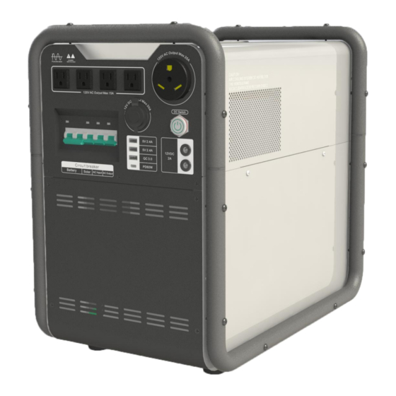
3. Unit diagram, operation instructions Guide 3.1 Top 120V AC 15A Outlets (NEMA 5-15R) Battery Breaker Solar Input breaker AC Input breaker AC Output breaker 120V AC 25A outlet (NEMA TT-30R) DC Output breaker 12VDC 20A outlet 12VDC 2A outlets. 5VDC Output (USB/Type-C sockets) Expansion battery connector Cooling fan... -
Page 5: Power On
3.3.2 Button Descriptions 3.3.4 LCD display 3.3.4.1 View the unit statuses : The “Home” or “Default” screens are the Button Description Status screens. A Status screen first appears when you turn on the unit. Power ON/ Press DOWN or UP to scroll through the seven different Status screens. Long press for 2s to turn ON/OFF. - Page 6 3.3.4.2 Function menu: From any Status screen, long press the Funct button 3.3.5 Parameter Settings for 5 seconds to enter the Function menu. Press DOWN or UP to scroll 3.3.5.1 AC Input Alarm setting through the different parameters P0-P4. Then, after reaching the desired From any Status screen, long press the Funct button for 5 seconds to enter parameter P0-P4, short press Funct to highlight that parameter’s setting (the the Function menu.
- Page 7 3.3.5.2 Inverter AC charging current setting From any Status screen, long press the Funct button for 5 seconds to enter 3.3.5.3 Error codes and solutions the Function menu. Press DOWN/UP until the Inverter charging current Error parameter “P3” is blinking. Press the Funct button to highlight the setting Problem Solution code...
- Page 8 3.3.5.4 Inverter working mode setting From any Status screen, long press the Funct button for 5 seconds to enter the Function menu. Press DOWN or UP until the inverter working mode parameter “P1” is blinking. Press the Funct button to highlight the setting (the work mode number “01,”...
- Page 9 4.2 System working diagram 4.3 Instructions for connecting Solar Power Pic 4-3b Use the correct size of extension PV cable (4 mm² or bigger) . Make sure the solar power voltage and wattage are within the allowed ranges 4.4 Instructions for connecting Expansion Battery (60VDC-150VDC, Max.
- Page 10 4.5 Instructions for AC input Use the correct size of AC power cable (4 , make sure mm² or bigger for 35A) the AC power voltage is in the allowed range ( . Plug AC 85VAC-138VAC) ⑬ power cord into the “AC input connector” .
- Page 11 4.7 Outputs 5. Power ON 4.7.1 AC outputs Note: Make sure voltages and polarities of external battery and 120VAC loads are connected to the “AC Output” ① outlets on the front solar panels are correct (see section 8) panel. The total continuous power of all combined AC loads should be no 5.1 Inverter Power ON more than the inverter’s rated continuous power of 3,000 watts.
- Page 12 5.3 Shutdown 5.5 Audio Alarms To properly shutdown: Turn off all loads and all energy inputs. Long press “AC Input The lack of AC Input does not the "ON/OFF" button for 2 seconds, releasing after the internal relay action Alarm” OFF sound an alarm.
-
Page 13: Maintenance
6. Maintenance 7. Simple Fault Diagnostics and Troubleshooting 6.1 The MPS-3K requires very little maintenance. The most important WARNING: There is high voltage inside the unit! Do not open for any maintenance practice is to follow basic rules of battery charging. This will reason. -
Page 14: Technical Data Sheet
8. Technical data sheet 9. Accessories Model: MPS3K-4500Wh 3ft. AC Intput Cord x1 3ft Solar Input Cord x1 & Connectors 120VAC / 3,000 W Continuous (6,000 W Rated AC Power Surge) Rated voltage 44.4VDC Battery Battery capacity 4,500 Wh Bank... -
Page 15: Reference Solar Array Wiring Diagrams
10. Reference Solar Array Wiring Diagrams 2) 250W(Voc=36V~42V) x 4 PCS (2 PCS in series for each string, 2 strings in parallel.) Total Solar Voltage Range: 60V~150V Wiring Diagram: Total Maximum Solar Power: 1,500 watts. 1) 250W(Voc=36V~42V) x 3 or 6 PCS (3 PCS in series for each string, all strings in parallel.) Wiring Diagram: 3) 300W(Voc=40V~45V)x 3 PCS (3 PCS in Series for each string) - Page 16 4) 300W(Voc=40V~45V) x 4 PCS (2 PCS in series for each string, 2 strings 6) 360W(Voc=45V~50V) x 3 PCS (3 PCS in series for each string) in parallel.) Wiring Diagram: Wiring Diagram: 7) 150W(Voc=20V~23V)x 8 or 10 PCS (4 or 5 PCS in Series for each string, 5) 360W(Voc=45V~50V) x 2 or 4 PCS (2 PCS in series for each string, all 2 strings in parallel) strings in parallel.)
-
Page 17: Bms On / Off / Reset
11. BMS On / Off / Reset To turn on the BMS, press and hold “Reset” button for 1 second. LED lights To turn off the BMS, press and hold the “Reset” button until the red light flash. To reset the BMS, press and hold “Reset” button for about 7 seconds, release it when all the LED lights on. -
Page 18: Rj45 Communication Port Instructions
2) Connection between the PC and BMS through the RS485. Instructions for LED indicator flash Flash Code Duration time for ON Duation time for OFF Flash 1 0.25 S 3.75 S Flash 2 0.5 S 0.5 S Flash 3 0.5 S 1.5 S 13.
Need help?
Do you have a question about the MPS3K-4500Wh and is the answer not in the manual?
Questions and answers