Table of Contents
Advertisement
Available languages
Available languages
Quick Links
Bedienungsanleitung
DE
EN
Plasma Schneidinverter / Plasma Cutting Inverter
IMPORTANT: Read this Owner's Manual Completely before attempting to use this
equipment. Save this manual and keep it handy for quick reference. Pay particular
attention to the safety instructions we have provided for your protection. Contact your
distributor if you do not fully understand this manual.
User Manual
PC 40 PFC
1.0004.0710-E
V1.0.20
Advertisement
Chapters
Table of Contents
Troubleshooting

Related Manuals for MK Welding PC 40 PFC


Summary of Contents for MK Welding PC 40 PFC
- Page 1 Bedienungsanleitung User Manual PC 40 PFC Plasma Schneidinverter / Plasma Cutting Inverter 1.0004.0710-E V1.0.20 IMPORTANT: Read this Owner’s Manual Completely before attempting to use this equipment. Save this manual and keep it handy for quick reference. Pay particular attention to the safety instructions we have provided for your protection. Contact your...
-
Page 2: Table Of Contents
Inhaltsverzeichnis Sicherheitsanweisung Betriebsbedingungen und Arbeitsumgebung Technische Daten Einschaltdauer Geräte Übersicht Schneiden Fehlerursachen - Behebung Prüfen und Warten Schematischer Schaltplan Ersatzteile Brenner Copyright © 2020 MK Trade GmbH, Wies, Österreich. Die Inhalte dieser Bedienungsanleitung sind alleiniges Eigentum der Firma MK Trade GmbH. Eine Weitergabe sowie Vervielfältigung dieses Dokuments, Verwertung und Mitteilung seines Inhalts sind verboten, soweit nicht ausdrücklich gestattet. -
Page 3: Sicherheitsanweisung
1. Sicherheitsanweisung Die Anlage ist ausschließlich für das Plasmaschneidverfahren bestimmt. Das Bedienungspersonal muss über die Sicherheitshinweise unterrichtet werden. Die Anlage darf unter keinen Umständen von ungeschultem Personal bedient werden. Reparaturen im elektrischen Bereich dürfen nur von Elektrofachkräften ausgeführt werden. Bei Pflege-, Wartungs- und Reparaturarbeiten sowie vor Öffnen des Gehäuses immer Netzstecker ziehen. - Page 4 Da der Bediener bei unsachgemäßem Gebrauch bzw. einem einfachen Defekt in Berührung kommen könnte, gelten erweiterte Sicherheitsmaßnahmen. Handschuhe und Schuhe sind zu tragen, die ausreichende Isolierung bieten. Die gesamte Kleidung ist trocken zu halten. Erhöhte Vorsicht gilt in einer Umgebung mit hoher Feuchtigkeit! Alle an der Anlage angeschlossenen elektrischen Leitungen sind auf einwandfreien Zustand zu überprüfen.
- Page 5 Entstehung von Rauchgasen bzw. toxischen Dämpfen kann zu Sauerstoffmangel in der Atemluft führen. Immer für ausreichend Frischluft sorgen! Gasflaschen stehen unter hohem Druck und stellen eine Gefahren- Quelle dar. Der richtige Umgang mit ihnen ist unbedingt beim Gaslieferanten zu erfragen. Beispielsweise müssen die Flaschen auf jeden Fall vor direkter Sonneneinstrahlung, vor offenem Feuer und starken Temperaturschwankungen, z.
- Page 6 8. Folgen sie den Betriebsregeln beim betätigen der Schalter und bei Justierungen. 9.Tragen sie beim Schneiden Schutzkleidung. Dies beinhaltet: ein langärmeliges T-Shirt / Lederärmel, Schutzschürze ohne Taschen, lange schützende Hosen, Arbeitsschuhe und Schutzbrille. Wenn sie mit heißem Material arbeiten, sollten sie Schutzhandschuhe tragen. Auch für Helfer gelten die gleichen Schutzmaßnahmen wie für Sie.
-
Page 7: Betriebsbedingungen Und Arbeitsumgebung
Das vorliegende Gerät ist mit CE gekennzeichnet und entspricht den gültigen Normen (EMC 2014/30/EU & LVD 2014/35/EU, EN 60974-10:2014 +A1:2015 und CISPR 11:2019 +A1:2010 (Absatz 4.1, 4.2 Gruppe 2, Klasse A), EN60974:2012). Parameter PC 40 PFC Eingangsspannung (V) ~90V - 275V, 50 / 60 Hz ~110/120/130V... -
Page 8: Einschaltdauer
4. Einschaltdauer Der Buchstabe „X“ steht für Einschaltdauer (Duty Cycle). Hierbei Einschaltdauer PC 40 PFC handelt es sich um den Teil der Zeit, in der ein Schweißgerät innerhalb eines bestimmten Zeitzyklus (10 Minuten) kontinuierlich mit seinem Ausgangsnennstrom schweißen kann. Die Beziehung zwischen dem Arbeitszyklus "X"... -
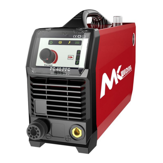
Page 9: Geräte Übersicht
5. Geräte Übersicht Brenner Zentral Anschluss Massekabel Wahltaster für Modus Luft Test, Vollmaterial, Gitter Schneiden Gitter Schneid Modus Vollmaterial Schneid Modus Luft Test Schneidstrom Aktiv LED Brenner Alarm LED (Fehler bei Brenner) Alarm LED (Überhitzung) Power LED 10 Schneidstrom Einstellung 11 Entleerungsventil Kondenswasser 12 Schauglas Kondenswasser 13 Druckmanometer Eingang... -
Page 10: Schneiden
6. Schneiden Betrieb mit Externe Luftzufuhr: - Schließen Sie das Netzkabel an (die Eingangsspannung finden Sie in der Rubrik Technische Daten und am Typenschild des Gerätes). - Schließen Sie den Brenner und das Massekabel an. - Schließen Sie den Druckluft Eingang mit der Luftversorgungsanlage an. - Schalten Sie den Netzschalter ein, die Kontrollleuchte „Power“... - Page 11 Techniker überprüft werden. - Sobald Brennerteile demontiert werden, bzw. die Teile zu sehr Verschlissen sind (dies kann auch zum defekt des Brenners führen, die Verschleißteile sind regelmäßig zu tauschen) leuchtet die Brenner Kontrollleuchte auf. - Die Druckluft sollte Trocken und Ölfrei sein, zu Nasse Druckluft bzw. Ölige Druckluft führt zum Frühzeitigen Verschleiß...
- Page 12 Achtung: Bei zu schneller Halten Sie den Brenner gerade Achten Sie beim Schneiden das Geschwindigkeit spritzen die und beobachten Sie den auf der Unterseite der Lichtbogen Funken nach Oben Lichtbogen während dem schön austritt. (Verletzungsgefahr) dies führt Schneidevorgang um einen (Achtung Funkenflug!) zum frühzeitigen / sofortigen sauberen Schnitt zu erzielen.
-
Page 13: Fehlerursachen - Behebung
7. Fehlerursachen - Behebung Fehler Mögliche Ursache Behebung Netz angeschlossen und Netzsicherung hat ausgelöst Netzsicherung prüfen Netzschalter auf „I“ – Netzanschluss unterbrochen Netzanschluss prüfen Kontrollleuchte Netz leuchtet nicht Alarmleuchte leuchtet Gerät ist Überhitzt Der Alarm wird nach Ablauf der Lüfterkühlung freigegeben und Sie können das Gerät neu starten Überstrom Die Alarmleuchte leuchtet... - Page 14 Monatlich - Das Gerät mit trockene Luft Ausblasen und Reinigen. Jährlich - Isolationsmessung Service und Kalibration des Gerätes. Bei nicht Durchführung erlischt die Garantie/ Gewährleistung. (Durchführung nur durch einem vom Hersteller autorisiertem Fachpersonal) Jegliche Arbeiten im und am Gerät, Änderungen usw. dürfen nur durch ein Autorisiertes Fachpersonal durchgeführt werden, ansonsten kann es zum Verfall der Zulassung führen und auch zum Erlöschen der Garantie / Gewährleistung.
-
Page 15: Schematischer Schaltplan
9. Schematischer Schaltplan... -
Page 16: Ersatzteile Brenner
10. Ersatzteile Brenner SCP/ SC 60 Brenner Kühlung: Luft Leistung: Einschaltdauer: Gas: Luft/N2 Luft Druck: 4.5-5,0 Bar (an der Düse) Durchflussmenge: 110l/min Zündung: Pilotlichtbogen / keine HF... - Page 17 PT/ IPT 60 Brenner...
- Page 19 CONTENT §1 Safety ........................2 §2 Overview ........................ 5 §2.1 Features ......................5 §2.2 Technical Data ..................... 5 §2.3 Working Principle ....................6 §2.4 Duty cycle and Over-heat ..................7 §2.5 Volt-Ampere Characteristic ................... 8 §3 Installation & Operation ..................9 §3.1 Layout for the front and rear panel .................
-
Page 20: Safety
§1 Safety Important Safety Precautions OPERATION AND MAINTENANCE OF PLASMA ARC EQUIPMENT CAN BE DANGEROUS TO YOUR HEALTH. l Plasma arc cutting produces intense electric and magnetic emissions that may interfere with the proper function of cardiac pacemakers, hearing aids, or other electronic health equipment. - Page 21 Remove all sources of these vapors. ELECTRIC SHOCK Electric Shock can injure or kill. The plasma arc process uses and produces high voltage electrical energy. This electric energy can cause severe or fatal shock to the operator or others in the workplace. l Never touch any parts that are electrically “live”...
- Page 22 PLASMA ARC RAYS Plasma Arc Rays can injure your eyes and burn your skin. The plasma arc process produces very bright ultra violet and infrared light. These arc rays will damage your eyes and burn your skin if you are not properly protected. l To protect your eyes, always wear a cutting helmet or shield.
-
Page 23: Overview
Air flow manual activation switch to set & test air pressure, pr- essure without the need to trigger the torch. Lightweight & compact design, ideal for portable applications. §2.2 Technical Data odels PC 40 PFC Parameters single-phase,90VAC-275VAC Input power(V) 50/60 Fre. -
Page 24: Working Principle
Adjustment range of current(A) 20~30 20~40 Max no-load voltage(V) 35% 30A 50% 40A SDuty cycle(40℃,10 minutes) 60% 22A 60% 36A 100% 20A 100% 30A Severance Cut for Carbon Steel ≤20 ≤25 (mm) Carbon steel ≤15 ≤20 Stainless steel ≤15 ≤20 Optimal cutting thickness (mm) Aluminum... -
Page 25: Duty Cycle And Over-Heat
continuously and steplessly to meet with the requirements of cutting craft. §2.4 Duty cycle and Over-heat The letter “X” stands for Duty Cycle, which is defined as the portion of the time a air plasma cutting machine can cut continuously with Relation of cutting current and duty cycle for PC 40 it’s rated output current within a certain time cycle... -
Page 26: Volt-Ampere Characteristic
§2.5 Volt-Ampere Characteristic CUT series of Air Plasma Cutting machines has excellent volt-ampere characteristic. Referring to the following graph. The relation between the rated loading voltage U and welding current I is as follows: When I ≤600A,U =80+0. 4 I (V);When 165A<I ≤500A,U =130+0. -
Page 27: Installation & Operation
§3 Installation & Operation §3.1 Layout for the front and rear panel (1) Plasma Torch Euro/ Central Connector. (2) Earth Lead Connection Socket. (3) Grid Cutting. (4) Normal Cutting (5) Check gas (6) Cutting Power Indicator: Lights when cutting power circuit activated . Torch System Error Indicator. - Page 28 Lights when issue with torch system or air supply detected and cutting output is disabled as a result. Flashing light means that torch shield installed. Continuous light means likely damaged or missing torch consumables or insufficient air pressure supply to the torch. Alarm Indicator (6) Lights when over voltage, over current or electrical overheating (due to exceeding duty cycle) is detected and protection is activated.
- Page 29 torch head and cable. This means it can create a small arc with some cutting power without making any electrical connection with the main machine earth. This is especially useful for starting cuts on material that does not have a good initial earth connection, such as paint, rust, scale.
-
Page 30: Installation & Operation
damaged torch head. It is also very important to only use genuine Strata consumables and parts XT4000 torch. They are engineered to suit the machine and non- genuine items may cause lack of performance, short life span, torch and machine damage and void warranty. - Page 31 Basic Operation 1) Connect the earth cable quick connector to the earth connection socket (2) Connect the earth clamp to the work piece. Contact with the work piece must be firm contact with clean, bare metal, with no corrosion, paint or scale at the contact point. 2) Connect the plasma torch to the machine central connector (1) ensuring the collar is done up firmly.
- Page 32 arc extinguishes. 6) In the post-flow mode, the arc be restarted immediately by depressing the torch switch. Turn on press Pre- Ignite the the cutting gas for pilot arc power switch source the torch shift to the leaves the Loose workpiece, workpiece, the pilot arc...
-
Page 33: Plasma Cutting Guide
§3.3 Plasma Cutting Guide §3.3.1 Cutting Guide Effect of Cutting Speed Piercing Technique NOTE: Keep moving while cutting. Cut at a steady speed without pausing. Maintain the cutting speed so that the arc lag is 10°to 20°behind the travel direction. Use a 5°- 15° leading angle in the direction of the cut. - Page 34 possibility of welding the tip to the plate. The torch should be angled at about 30° when starting to pierce, and then straightened after accomplishing the pierce. 2. Grate Cutting - For rapid restarts, such as grate or heavy mesh cutting, do not release the torch switch.
- Page 35 After cutting arc is established, move the torch in the desired direction keeping the torch tip slightly angled, maintaining contact with the work piece. Avoid moving too fast as would be indicated by sparks radiating from the topside of the work piece. Move the torch just fast enough to maintain sparks concentration at the underside of the work piece and making sure the material is completely cut through before moving on.
-
Page 36: Troubleshooting
dross build-up on underside of cut. Experiment with adjusting current and speed to minimize dross. When dross is present on carbon steel, it is commonly referred to as either ‘high speed, slow speed, or top dross’. Dross present on top of the plate is normally caused by too great a torch to plate distance. -
Page 37: Operation Environment
1. Increase speed until problem 1. Cutting speed too slow solved 2. Torch is too high, away from 2. Lower torch Arc stops while material recommended height cutting 3. Worn torch parts 3. Inspect repair or 4. Work piece earth cable replace worn parts disconnected 4. -
Page 38: Operation Notices
▲ The content of dust, acid, corrosive gas in the surrounding air or substance cannot exceed normal standard. ▲ Take care that there is sufficient ventilation during welding. There must be at least 30cm free distance between the machine and wall. §3.6 Operation Notices ▲... -
Page 39: Maintenance & Troubleshooting
§4 Maintenance & Troubleshooting §4.1 Cutting gun maintenance Warning : 1. Check the consumable parts for damage, if worn, replace it. 2. Turn off the power source before check or remove cutting gun parts Note: When operating the torch in a normal condition, a small amount of gas vents through the gap between the shield cup and the torch handle, Do not attempt to over tighten the shield cup as irreparable damage to internal components may result. - Page 40 A. Power lamp and temperature lamp on. 1. Air flow blocked, check for blocked air flow around the unit and correct condition. 2. Fan blocked, check and correct condition. 3. Unit is overheated, let unit cool down for at least 5 minutes. Make sure the unit has not been operated beyond Duty Cycle limit, refer to technology parameters in Section 2.
- Page 41 2. Faulty components in unit, return for repair or have qualified technician repair. E. Difficult Starting 1. Worn torch parts (consumables), shut off input power. Remove and inspect torch shield cup, tip and electrode. Replace electrode or tip if worn; replace shield cup if excessive spatter adheres to it.
-
Page 42: Electrical Schematic Drawing
§4.3 Electrical schematic drawing... - Page 43 Produkt Marke: MK Welding Produkt Gruppe: Schneiden Produkt Type: Plasmaschneider Bezeichnung des Produktes: PC 40 PFC Seriennummer*: 1.0004.0710-E _____________________ Baujahr*: 20_________ (Ersichtlich anhand der Seriennummer) * anhand des Typenschildes am Gerät Auszufüllen Das oben genannte Erzeugnis stimmt mit den Vorschriften folgender Europäischen Richtlinien überein:...
Need help?
Do you have a question about the PC 40 PFC and is the answer not in the manual?
Questions and answers